Version 1.2, updated 2022-06-01
So, now that we have our window and the associated surface ready, let’s get started implementing our graphics pipeline. Obviously, to be able to do that, it might help to understand how a graphics pipeline actually works.
The logical graphics pipeline
Like the compute pipeline, the graphics pipeline takes some input data, processes it and outputs the result. The key difference is that while a compute pipeline is pretty much ‚general purpose‘, the graphics pipeline is tailored to a very specific use case: to transform a 3D world that is made of thousands of primitives (usually triangles) into a 2D image of that world. Where the compute pipeline only has one processing stage that is freely programmable, a graphics pipeline has at least five stages with clearly defined responsibilities. Some of those stages are fixed in their functionality, the behaviour of others is controlled by a shader program that we provide (like the compute shader). Each stage takes the output of the previous one as its input – hence the name pipeline.
So let’s look at the logical structure of a Vulkan graphics pipeline:
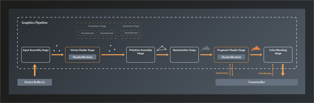
The main input to the graphics pipeline is a collection of so-called vertices1 that are stored in a specific type of buffer. Technically speaking, a vertex is just a tuple of values that don’t have any predefined meaning. In practice however it is almost always the coordinates of a point in 3D space plus associated attributes such as e.g. it’s color, the corresponding texture index and so on. These vertices are the corners of all the primitives that make up the 3D world we want to render.
The first stage of the pipeline itself is the Input Assembly Stage. This is a fixed stage whose main responsibility is to collect the vertex input data from the specified buffer(s) and to ensure that the right vertices in the right order are passed on to the vertex shader stage. This enables e.g. re-using vertices that are shared between multiple primitives and thus saving memory bandwidth.
Next in line is the Vertex Shader Stage. This is one of the programmable stages, and it’s the only one that is mandatory to be specified. So we are always required to write a vertex shader. This shader’s main responsibility is to transform one input vertex coordinate to an output coordinate so that it ends up in the right position in our 3D world, relative to the location of our virtual camera. We’ll talk about this process in more detail later in this series. The vertex shader may also perform additional tasks like e.g. per-vertex lighting calculations.
Tesselation and Geometry Stage are also programmable, but they are optional and we won’t be using them for now. I therefore won’t go into details here. Suffice it to say that they can be used to let the GPU create additional vertices to add geometry to the scene and improve the level of detail.
The Primitive Assembly is a fixed stage that takes the processed (and – if we have tesselation and / or geometry shaders – generated ) vertices and groups them into primitives by using the information from the input assembly stage. Without this step, the next stage would not be able to do its job as it would still only see individual vertices and couldn’t process primitives as a whole. The primitive assembly stage is also the one that applies the viewport transformation, i.e. it transforms vertices from normalized 3D device coordinates into 2D image coordinates.
Rasterization is another fixed stage whose main job it is to transform the logical representation of a primitive (up to now those are still defined by their vertices) into a collection of so-called fragments that are interpolated between the vertices and make up the actual visual shape on your screen2. The rasterization stage is also responsible for operations like back-face culling and depth clamping (more on those later), and to determine whether the geometry ultimately is drawn as points, lines or filled shapes.
Each fragment is then sent to the next stage: the Fragment Shader. This is a programmable stage that is run once per fragment3, usually primarily to determine its color as a result of lighting and surface properties. Depth testing and multisampling – if enabled – also happen in the context of the fragment shader stage. It is actually not mandatory to provide a shader for this stage and there are use cases where it makes sense to omit that4. We want to generate output on the screen however, so we will write a fragment shader.
And finally the Color Blending Stage. This is where the color of each new fragment is merged with the already existing color value at the respective location. Depending on the configuration of this stage, this allows for hardware-accelerated transparency, translucency etc.
The output data of the graphics pipeline is stored in a so called framebuffer. In the simplest case the output is just one rendered image, but the framebuffer can hold multiple of those, e.g. for also storing the depth values for each fragment. This is why the fragment shader stage and the color blending stage have to interact with the framebuffer instead of just writing to it.
Creating the graphics pipeline
Okay, so much for the theory. Let’s look at how we can create a graphics pipeline in practice. We’ve actually already had a brief look at the needed function back in lesson 8:
class Device
{
    ...
    // return values are actually ResultValue< UniquePipeline >, see chapter 2
    UniquePipeline createGraphicsPipelineUnique( PipelineCache pipelineCache, const GraphicsPipelineCreateInfo& createInfo, ... );
    ...
};
So the only difference compared to creating a compute pipeline is that this time we need a GraphicsPipelineCreateInfo. So let’s have a look at that one:
struct GraphicsPipelineCreateInfo
{
    ...
    GraphicsPipelineCreateInfo& setFlags( PipelineCreateFlags flags_ )
    GraphicsPipelineCreateInfo& setStages( const container_t< const PipelineShaderStageCreateInfo >& stages_ );
    GraphicsPipelineCreateInfo& setPVertexInputState( const PipelineVertexInputStateCreateInfo* pVertexInputState_ );
    GraphicsPipelineCreateInfo& setPInputAssemblyState( const PipelineInputAssemblyStateCreateInfo* pInputAssemblyState_ );
    GraphicsPipelineCreateInfo& setPTessellationState( const PipelineTessellationStateCreateInfo* pTesselationState_ );
    GraphicsPipelineCreateInfo& setPViewportState( const PipelineViewportStateCreateInfo* pViewportState_ )
    GraphicsPipelineCreateInfo& setPRasterizationState( const PipelineRasterizationStateCreateInfo* pRasterizationState_ );
    GraphicsPipelineCreateInfo& setPMultisampleState( const PipelineMultisampleStateCreateInfo* pMultisampleState_ );
    GraphicsPipelineCreateInfo& setPDepthStencilState( const PipelineDepthStencilStateCreateInfo* pDepthStencilState_ );
    GraphicsPipelineCreateInfo& setPColorBlendState( const PipelineColorBlendStateCreateInfo* pColorBlendState_ );
    GraphicsPipelineCreateInfo& setPDynamicState( const PipelineDynamicStateCreateInfo* pDynamicState_ );
    GraphicsPipelineCreateInfo& setLayout( PipelineLayout layout_ );
    GraphicsPipelineCreateInfo& setRenderPass( RenderPass renderPass_ );
    GraphicsPipelineCreateInfo& setSubpass( uint32_t subpass_ );
    GraphicsPipelineCreateInfo& setBasePipelineHandle( Pipeline basePipelineHandle_ );
    GraphicsPipelineCreateInfo& setBasePipelineIndex( int32_t basePipelineIndex_ );
    ...
};
At first sight that seems quite a lot of stuff to configure. But compare this interface to the logical structure I described above – a lot of this should already bear some meaning for you by now. Anyway, let’s go through the functions one by one quickly (we’ll cover the relevant ones in more detail later):
- there are several
PipelineCreateFlagsthat we could set (quite many actually since Vulkan version 1.1), but since none of them is relevant for us at this point we once more leave the flags alone - this time we can set multiple
stages_, not just one as for the compute pipeline. And that makes sense, as we just learned that there are the vertex, geometry, tesselation and fragment shader stages that we can define for a graphics pipeline. setPVertexInputState, as it’s name suggests, describes the vertex input to the pipeline, i.e. where to find and how to interpret the vertex data. I didn’t list this as a separate stage in the overview above because to my knowledge there is no actual functionality associated with the vertex input state. It’s really just a bit of information that we need to pass to the pipeline.pInputAssemblyState_unsurprisingly determines the behavior of the input assembly stage- since we won’t use tesselation,
setPTesselationStateis not of any interest for us right now pViewportStatespecifies the configurable part of the primitive assembly stage. As described above, this is controlling how 3D world coordinates are converted into 2D framebuffer coordinates.pRasterizationState_is hopefully self-explanatory again- multisampling is a technique to improve the visual quality, especially of edges, by computing multiple fragments per screen pixel and then outputting an average. We won’t be using this feature until later in this series, however, Vulkan requires us to define and set a
pMultisampleState_. - we also won’t need
pDepthStencilState_for now as we’re only going to draw a single triangle initially and therefore don’t have to deal with depth testing yet pColorBlendState_is important again but should be conceptually clear as well- in general pipelines in Vulkan are fixed, which means that you cannot change them after creation. That has a lot of advantages for the drivers ability to optimize the pipeline performance. But the flip-side of that is that you have to re-create the pipeline every time parts of the configuration change. That would be very wasteful in a scenario where such changes happen frequently. Therefore Vulkan allows you to mark parts of the pipeline as dynamic upfront, so that you can apply changes without having to recreate the whole pipeline. Our pipeline will not be changing, so we will ignore
setPDynamicState - You may remember that we had to create a
PipelineLayoutfor our compute pipeline, and that this was used to set up the descriptors. We will start out without specifying any data input to the pipeline, so we can just use an empty layout for now. - the
RenderPassis difficult to explain in a few words. We’ll look at this one in more depth when we actually get to creating one. For now suffice it to say that a render pass describes the target structures the pipeline renders to - and finally there’s the two functions relating to the base pipeline. Those become relevant when you derive similar pipelines from a common base pipeline in order to be able to switch among them rapidly. We won’t be using this feature either.
Alright, we now have an overview on what we need to do to create a render pipeline. Let’s finish today’s lesson by preparing the corresponding function:
vk::UniquePipeline create_graphics_pipeline( const vk::Device& logicalDevice )
{
    const auto pipelineCreateInfo = vk::GraphicsPipelineCreateInfo{};

    return logicalDevice.createGraphicsPipelineUnique(
        vk::PipelineCache{},
        pipelineCreateInfo ).value;
}
And to check whether that function is actually working, let’s already call it from main:
int main()
{
    try
    {
        ...

        const auto pipeline = create_graphics_pipeline( logicalDevice );

        while ( !glfwWindowShouldClose( window.get() ) )
        {
            glfwPollEvents();
        }
    }
    catch( const std::exception& e )
    {
        std::cout << "Exception thrown: " << e.what() << "\n";
        return -1;
    }
    return 0;
}
If you compile and run this now, you’ll get a lot of validation errors and an exception. This is okay for now because our pipelineCreateInfo doesn’t really contain any information yet and so Vulkan doesn’t know what to do. Starting next time we’ll fill the create info with the proper data.
- In reality there usually is also other input like vertex indices, global variables (aka uniforms) etc. They are not relevant for understanding the basic principles of the pipeline though, therefore I’m ignoring them at this point.
- A fragment is basically a position in the 2D space of the framebuffer with an associated a depth value, plus potentially some interpolated data from previous stages. For simplicity you can think of the fragments as the pixels of the image that are finally drawn on the screen, although this is not really accurate as there is not always a 1:1 equivalence between a fragment and a pixel (e.g. in the presence of multisampling).
- It’s good to keep in mind that the fragment shader, since it is run a lot more often than the other shaders, has a significant impact on the overall processing time of the pipeline.
- This makes sense e.g. when you’re only interested in the depth value of a fragment because you’re doing shadow mapping or a related technique