Lesson 26: Depth Testing

Version 1.1, updated 2022-12-22

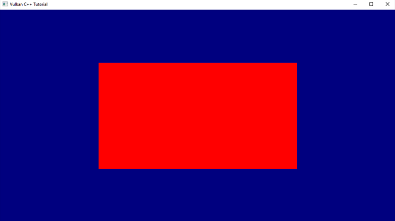
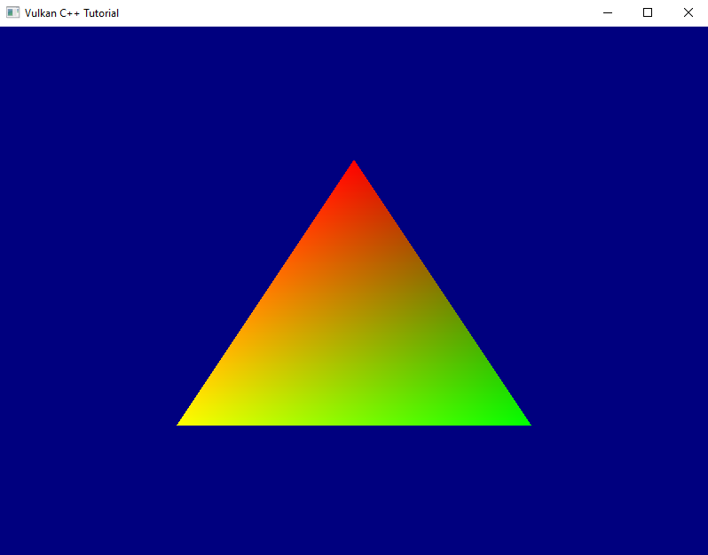
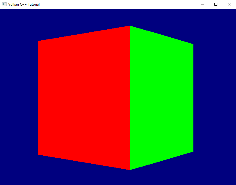
Many of you have probably already spotted the problem that makes our rotating cube look so weird: we did not yet enable depth testing. Our pipeline just renders the geometry in the order in which it is coming in and does not care which triangle is actually closer to the camera. The result is that the red front face is rendered first, but because it is covered completely by all the other faces which are rendered afterwards we never get to see it. For the same reason the top and bottom faces are always completely visible – they are rendered last on top of everything else.

So let’s go and fix this. The first thing to do is to enable depth-testing in the pipeline. To do so we need to create a PipelineDepthStencilStateCreateInfo and pass it to our GraphicsPipelineCreateInfo.

PipelineDepthStencilStateCreateInfo looks like this:

struct PipelineDepthStencilStateCreateInfo
{
    ...
    PipelineDepthStencilStateCreateInfo& setFlags( vk::PipelineDepthStencilStateCreateFlags flags_ );
    PipelineDepthStencilStateCreateInfo& setDepthTestEnable( vk::Bool32 depthTestEnable_ ) 
    PipelineDepthStencilStateCreateInfo& setDepthWriteEnable( vk::Bool32 depthWriteEnable_ );
    PipelineDepthStencilStateCreateInfo& setDepthCompareOp( vk::CompareOp depthCompareOp_ );
    PipelineDepthStencilStateCreateInfo& setDepthBoundsTestEnable( vk::Bool32 depthBoundsTestEnable_ );
    PipelineDepthStencilStateCreateInfo& setMinDepthBounds( float minDepthBounds_ );
    PipelineDepthStencilStateCreateInfo& setMaxDepthBounds( float maxDepthBounds_ );
    PipelineDepthStencilStateCreateInfo& setStencilTestEnable( vk::Bool32 stencilTestEnable_ );
    PipelineDepthStencilStateCreateInfo& setFront( const vk::StencilOpState& front_ );
    PipelineDepthStencilStateCreateInfo& setBack( const vk::StencilOpState& back_ );    
    ...
};
  • once more we can ignore the flags_ because there are none defined
  • setDepthTestEnable enables / disables the actual depth test itself, i.e. the comparison between the new fragment and the value that is currently in the depth buffer for that fragment coordinate. Fragments that fail this test are not processed any further.
  • setDepthWriteEnable specifies whether the new depth value is actually written to the depth buffer. In most cases you’ll want to set this to true1.
  • setDepthCompareOp allows you to specify the function that is used for comparing the new depth value with the old one. In most cases this will be CompareOp::eLess but there might be situations where a different comparison is required.
  • setDepthBoundsTestEnable specifies if the depth values are tested also against  minDepthBounds_ and maxDepthBounds_ and are discarded if they’re outside of this range.
  • stencil testing, which you can activate with setStencilTestEnable, is a technique that allows you to only render certain portions of the scene. Insofar it is similar to the scissor operation (see lesson 16), but much more powerful. Essentially this looks at the stencil value for this fragment in the buffer and discards the fragment if a certain condition for that value is not met.
  • setFront and setBack are related to the stencil test. We won’t use that feature for now, therefore we can ignore those two functions (their parameter is a bit more involved, so I don’t want to go into that here).

Alright, let’s enable depth testing for our pipeline:

vk::UniquePipeline create_graphics_pipeline(
    const vk::Device& logicalDevice,
    const vk::ShaderModule& vertexShader,
    const vk::ShaderModule& fragmentShader,
    const vk::RenderPass& renderPass,
    const vk::Extent2D& viewportExtent,
    const std::vector< vk::Format >& vertexFormats
)
{
    ...
    const auto depthStencilState = vk::PipelineDepthStencilStateCreateInfo{}
        .setDepthTestEnable( true )
        .setDepthWriteEnable( true )
        .setDepthCompareOp( vk::CompareOp::eLess )
        .setDepthBoundsTestEnable( false )
        .setStencilTestEnable( false );

    const auto pipelineCreateInfo = vk::GraphicsPipelineCreateInfo{}
        .setStages( shaderStageInfos )
        .setPVertexInputState( &vertexInputState )
        .setPInputAssemblyState( &inputAssemblyState )
        .setPViewportState( &viewportState )
        .setPRasterizationState( &rasterizationState )
        .setPMultisampleState( &multisampleState )
        .setPDepthStencilState( &depthStencilState )
        .setPColorBlendState( &colorBlendState )
        .setLayout( *pipelineLayout )
        .setRenderPass( renderPass );
    ...
}

That is of course not enough. A depth test needs an image attachment to store the depth values, and we did not create one so far. Let’s change that:

vk::UniqueRenderPass create_render_pass(
    const vk::Device& logicalDevice,
    const vk::Format& colorFormat
)
{
    ...
    const auto depthAttachment = vk::AttachmentDescription{}
        .setFormat( vk::Format::eD32Sfloat )
        .setSamples( vk::SampleCountFlagBits::e1 )
        .setLoadOp( vk::AttachmentLoadOp::eClear )
        .setStoreOp( vk::AttachmentStoreOp::eDontCare )
        .setStencilLoadOp( vk::AttachmentLoadOp::eDontCare )
        .setStencilStoreOp( vk::AttachmentStoreOp::eDontCare )
        .setInitialLayout( vk::ImageLayout::eUndefined )
        .setFinalLayout( vk::ImageLayout::eDepthStencilAttachmentOptimal );

    const auto depthAttachmentRef = vk::AttachmentReference{}
        .setAttachment( 1 )
        .setLayout( vk::ImageLayout::eDepthStencilAttachmentOptimal );

    const auto subpass = vk::SubpassDescription{}
        .setPipelineBindPoint( vk::PipelineBindPoint::eGraphics )
        .setPDepthStencilAttachment( &depthAttachmentRef )
        .setColorAttachments( colorAttachmentRef );

    const auto attachments = std::array< vk::AttachmentDescription, 2>{ colorAttachment, depthAttachment };
    const auto renderPassCreateInfo = vk::RenderPassCreateInfo{}
        .setAttachments( attachments )
        .setSubpasses( subpass );
    ...
}

We’ve talked about attachments and subpasses quite a bit back in lesson 17. The relevant changes for a depth attachment are the format (we only need one float value per fragment, hence the eD32Sfloat2) and the final layout. Everything else is the same as for the color attachment.

Running this version yields an exception and a validation error:

... VkFramebufferCreateInfo attachmentCount of 1 does not match attachmentCount of 2 of VkRenderPass ...

Of course. Our pipeline now expects the framebuffer to come with a depth attachment, which of course it doesn’t have yet. Let’s fix that by pretending we already have a depth image view that we could pass to the framebuffer creation function:

std::vector< vk::UniqueFramebuffer > create_framebuffers(
    const vk::Device& logicalDevice,
    const std::vector< vk::UniqueImageView >& imageViews,
    const vk::ImageView& depthImageView,
    const vk::Extent2D& imageExtent,
    const vk::RenderPass& renderPass
)
{
    std::vector< vk::UniqueFramebuffer > result;
    for( const auto& v : imageViews )
    {
        std::array< vk::ImageView, 2 > attachments = { *v, depthImageView };
        const auto frameBufferCreateInfo = vk::FramebufferCreateInfo{}
            .setRenderPass( renderPass )
            .setAttachments( attachments )
            .setWidth( imageExtent.width )
            .setHeight( imageExtent.height )
            .setLayers( 1 );

        result.push_back( logicalDevice.createFramebufferUnique( frameBufferCreateInfo ) );
    }

    return result;
}

We only need one depth image view because it is only used during the actual rendering and we only ever draw a single frame at the same time.

So far, so good, unfortunately we don’t have a depth image view yet. Where do we get that from? The imageViews for the rendering output are members of our swapchain class, so it seems logical that it also owned the depth image. However, while the former are created for us by the SwapchainKHR class we will have to do it ourselves for the depth image. The logical device gives us what we need:

class Device
{
    ...
    UniqueImage createImageUnique( const ImageCreateInfo& createInfo, ... ) const;
    ...
};

… with:

struct ImageCreateInfo
{
    ...
    ImageCreateInfo& setFlags( vk::ImageCreateFlags flags_ );
    ImageCreateInfo& setImageType( vk::ImageType imageType_ );
    ImageCreateInfo& setFormat( vk::Format format_ );
    ImageCreateInfo& setExtent( const vk::Extent3D& extent_ );
    ImageCreateInfo& setMipLevels( uint32_t mipLevels_ );
    ImageCreateInfo& setArrayLayers( uint32_t arrayLayers_ );
    ImageCreateInfo& setSamples( vk::SampleCountFlagBits samples_ );
    ImageCreateInfo& setTiling( vk::ImageTiling tiling_ );
    ImageCreateInfo& setUsage( vk::ImageUsageFlags usage_ );
    ImageCreateInfo& setSharingMode( vk::SharingMode sharingMode_ );
    ImageCreateInfo& setQueueFamilyIndices( const container_t<const uint32_t>& queueFamilyIndices_ )
    ImageCreateInfo& setInitialLayout( vk::ImageLayout initialLayout_ );
    ...
}

Wow, not that easy, given that we just would like to have an image. Anyway, let’s unpack:

  • there are actually quite a number of ImageCreateFlags defined. However, we don’t need any of them yet.
  • the imageType_ specifies whether we want to create a 1d, 2d or 3d image
  • the Format parameter should be familiar by now. For the depth image we obviously should use the same format that we specified for our attachment above
  • the extent_ defines the dimensions of the image to create. It’s a 3D extent so that the same function can cover all use cases (Vulkan is a C interface, so there are no overloads possible), we can just set the 3rd dimension to 1
  • the mipLevels_ parameter relates to a technique called mip mapping. I won’t go into details here, suffice it to say that it uses the same image in different resolutions to mitigate rendering artefacts when a textured object is further away from the camera. We don’t use this technique yet, so we can set this parameter to 1.
  • we talked about arrayLayers back in lesson 18. We’re still not going to use this technique here, so we set this parameter to 1 as well
  • samples_ is again the number of multisample fragments rendered for each pixel on screen.
  • the tiling parameter controls the internal layout of the image data in GPU memory. We don’t have any special requirements here, so we just use eOptimal.
  • usage_ specifies how we intend to use this image in the pipeline.
  • the sharingMode_ specifies whether the image is going to be used by multiple queues
  • the queueFamilyIndices_ are only relevant in cases where the image is going to be shared between queues, i.e. where the sharing mode is eConcurrent
  • initialLayout – just as for the attachment descriptions – specifies the initial layout that this image will have.

With that knowledge, let’s create a first version of our depth image creation:

gpu_image create_depth_image(
    const vk::Device& logicalDevice,
    const vk::Extent2D& imageExtent
)
{
    const auto createInfo = vk::ImageCreateInfo{}
        .setImageType( vk::ImageType::e2D )
        .setFormat( vk::Format::eD32Sfloat )
        .setExtent( vk::Extent3D{ imageExtent.width, imageExtent.height, 1 } )
        .setMipLevels( 1 )
        .setArrayLayers( 1 )
        .setSamples( vk::SampleCountFlagBits::e1 )
        .setTiling( vk::ImageTiling::eOptimal )
        .setUsage( vk::ImageUsageFlagBits::eDepthStencilAttachment )
        .setSharingMode( vk::SharingMode::eExclusive )
        .setInitialLayout( vk::ImageLayout::eUndefined );
    return logicalDevice.createImageUnique( createInfo );
}

We’re not done here though. Remember how it wasn’t enough to create a vk::Buffer but instead we needed to explicitly allocate the memory for it? We need to do exactly the same here. Let’s therefore create an equivalent to our gpu_image struct:

struct gpu_image
{
    vk::UniqueImage image;
    vk::UniqueDeviceMemory memory;
};

… and expand our create_depth_image function to also allocate the memory:

gpu_image create_depth_image(
    const vk::PhysicalDevice& physicalDevice,
    const vk::Device& logicalDevice,
    const vk::Extent2D& imageExtent
)
{
    const auto createInfo = ...
    auto image = logicalDevice.createImageUnique( createInfo );

    const auto memoryRequirements = logicalDevice.getImageMemoryRequirements( *image );
    const auto memoryProperties = physicalDevice.getMemoryProperties();

    const auto memoryIndex = vcpp::find_suitable_memory_index(
        memoryProperties,
        memoryRequirements.memoryTypeBits,
        vk::MemoryPropertyFlagBits::eDeviceLocal );

    const auto allocateInfo = vk::MemoryAllocateInfo{}
        .setAllocationSize( memoryRequirements.size )
        .setMemoryTypeIndex( memoryIndex );

    auto memory = logicalDevice.allocateMemoryUnique( allocateInfo );
    logicalDevice.bindImageMemory( *image, *memory, 0u );

    return { std::move( image ), std::move( memory ) };
}

With that function we can create the image, but create_framebuffer needs an ImageView. Well, that shouldn’t be too hard, we already have create_image_view to create an ImageView from an image. The problem is that this function currently has the ImageAspectFlags hardcoded to eColor. We need to set a flag of eDepth, so we need to expose that parameter:

vk::UniqueImageView create_image_view(
    const vk::Device& logicalDevice,
    const vk::Image& image,
    const vk::Format& format,
    const vk::ImageAspectFlags flags = vk::ImageAspectFlagBits::eColor
)
{
    const auto subresourceRange = vk::ImageSubresourceRange{}
        .setAspectMask( flags )
        ...
}

As said above, the swapchain should own the depth image and the image view and pass it on to the framebuffer creation. So we need to adjust the swapchain constructor a bit to actually create them:

swapchain::swapchain(
    const vk::PhysicalDevice& physicalDevice,
    const vk::Device& logicalDevice,
    const vk::RenderPass& renderPass,
    const vk::SurfaceKHR& surface,
    const vk::SurfaceFormatKHR& surfaceFormat,
    const vk::Extent2D& imageExtent,
    std::uint32_t maxImagesInFlight
)
    : m_logicalDevice{ logicalDevice }
    , m_swapchain{ create_swapchain( logicalDevice, surface, surfaceFormat, imageExtent, maxImagesInFlight ) }
    , m_maxImagesInFlight{ maxImagesInFlight }
    , m_imageViews{ create_swapchain_image_views( logicalDevice, *m_swapchain, surfaceFormat.format ) }
    , m_depthImage{ create_depth_image( physicalDevice, logicalDevice, imageExtent ) }
    , m_depthImageView{ create_image_view( 
        logicalDevice, 
        *m_depthImage.image, 
        vk::Format::eD32Sfloat, 
        vk::ImageAspectFlagBits::eDepth ) }
{
    m_framebuffers = create_framebuffers( logicalDevice, m_imageViews, *m_depthImageView, imageExtent, renderPass );
    ...
}

Obviously we need to adjust the constructor call in main accordingly as well. This version compiles, but it doesn’t render anything and we get a lot of validation errors:

... VkRenderPassBeginInfo struct has a clearValueCount of 1 but there must be at least 2 entries in pClearValues array to account for the highest index attachment in VkRenderPass ...

Once again the fact that Vulkan really only does what we ask it to do bites us: we have created a depth attachment for our render pass, but we didn’t specify a clear value for that attachment. That means that the depth buffer contains arbitrary garbage and so the depth testing cannot work propoerly. The solution is pretty trivial: we already specify a clear value for the color attachment, so we just need to extend that code a bit:

void record_command_buffer(
    const vk::CommandBuffer& commandBuffer,
    const vk::Pipeline& pipeline,
    const vk::RenderPass& renderPass,
    const vk::Framebuffer& frameBuffer,
    const vk::Extent2D& renderExtent,
    const vk::Buffer& vertexBuffer,
    const std::uint32_t vertexCount
)
{
    const auto clearValues = std::array< vk::ClearValue, 2 >{
        vk::ClearValue{}.setColor( std::array< float, 4 >{ { 0.f, 0.f, .5f, 1.f } } ),
        vk::ClearValue{}.setDepthStencil( vk::ClearDepthStencilValue{ 1.f, 0 } )
    };
    ...
}

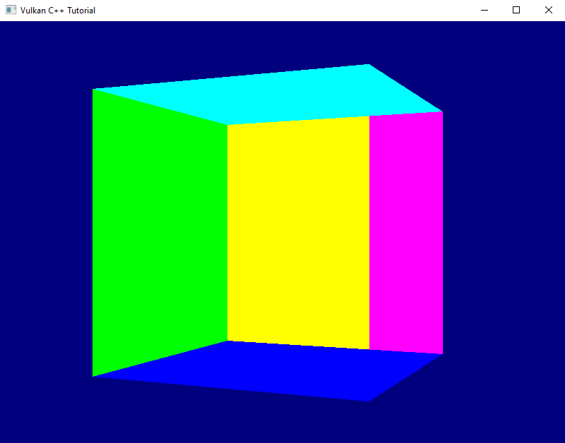
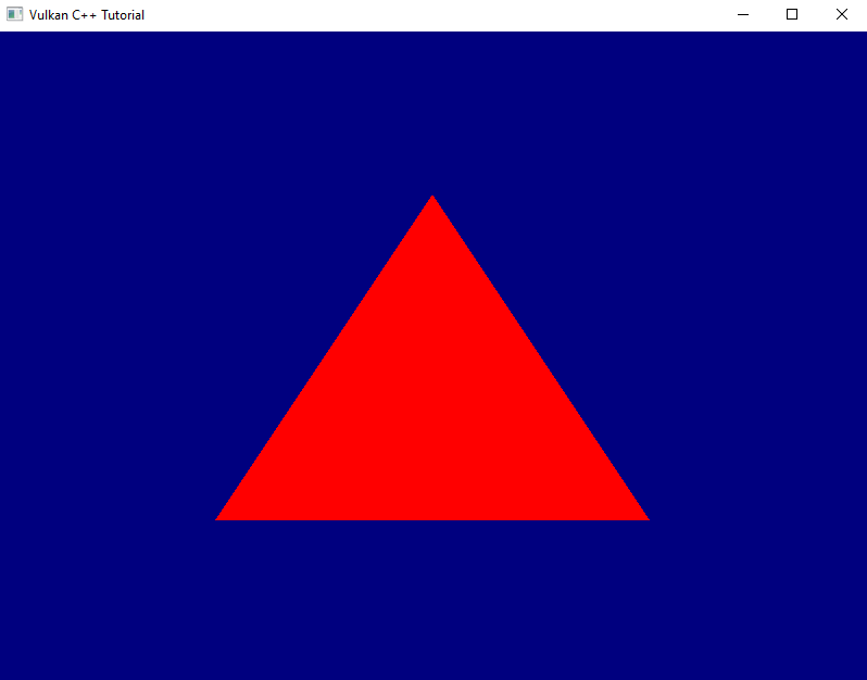
And now we see a correctly rendered rotating cube on screen. Yay!

Vulkan C++ Tutorial: Screenshot showing a perspective rendering of the cube without errors
Fig. 1: We finally see a correctly rendered cube

Before I finish, an apology: last time I promised to also improve the render loop. However, it turned out that this lesson is long enough already. Therefore the improvement will have to wait until next time.


  1. Note that if depth writing is enabled, the depth values will be calculated and written to the depth image even if you disable the actual testing. This can be useful for certain special effects.
  2. Strictly speaking this format might not be available on all hardware, so in a real-world application you probably should design for some more flexibility

Lesson 25: Going 3D

Version 1.0, updated 2022-11-27

So far all that we’ve created is one flat triangle, which is still pretty far from a proper 3D scene. I think it’s time to change this.

Our vertices already have three dimensional coordinates, only that we’re not using the third dimension yet. So we should be able to create a three-dimensional object without any changes to the pipeline. Let’s modify our vertex buffer to contain a cube:

constexpr size_t vertexCount = 36;
const std::array< float, 8 * vertexCount > vertices = {
    // front               (red)
    -.5f, -.5f, .5f, 1.f,  1.f, 0.f, 0.f, 1.f,
    .5f, -.5f, .5f, 1.f,   1.f, 0.f, 0.f, 1.f,
    -.5f, .5f, .5f, 1.f,   1.f, 0.f, 0.f, 1.f,
    .5f, -.5f, .5f, 1.f,   1.f, 0.f, 0.f, 1.f,
    .5f, .5f, .5f, 1.f,    1.f, 0.f, 0.f, 1.f,
    -.5f, .5f, .5f, 1.f,   1.f, 0.f, 0.f, 1.f,
    
    // back                (yellow)
    -.5f, -.5f, -.5f, 1.f, 1.f, 1.f, 0.f, 1.f,
    .5f, -.5f, -.5f, 1.f,  1.f, 1.f, 0.f, 1.f,
    -.5f, .5f, -.5f, 1.f,  1.f, 1.f, 0.f, 1.f,
    .5f, -.5f, -.5f, 1.f,  1.f, 1.f, 0.f, 1.f,
    .5f, .5f, -.5f, 1.f,   1.f, 1.f, 0.f, 1.f,
    -.5f, .5f, -.5f, 1.f,  1.f, 1.f, 0.f, 1.f,

    // left                (violet)
    -.5f, -.5f, .5f, 1.f,  1.f, 0.f, 1.f, 1.f,
    -.5f, -.5f, -.5f, 1.f, 1.f, 0.f, 1.f, 1.f,
    -.5f, .5f, .5f, 1.f,   1.f, 0.f, 1.f, 1.f,
    -.5f, -.5f, .5f, 1.f,  1.f, 0.f, 1.f, 1.f,
    -.5f, .5f, -.5f, 1.f,  1.f, 0.f, 1.f, 1.f,
    -.5f, .5f, .5f, 1.f,   1.f, 0.f, 1.f, 1.f,

    // right               (green)
    .5f, -.5f, .5f, 1.f,   0.f, 1.f, 0.f, 1.f,
    .5f, -.5f, -.5f, 1.f,  0.f, 1.f, 0.f, 1.f,
    .5f, .5f, -.5f, 1.f,   0.f, 1.f, 0.f, 1.f,
    .5f, -.5f, .5f, 1.f,   0.f, 1.f, 0.f, 1.f,
    .5f, .5f, -.5f, 1.f,   0.f, 1.f, 0.f, 1.f,
    .5f, .5f, .5f, 1.f,    0.f, 1.f, 0.f, 1.f,

    // top                 (turquoise)
    -.5f, -.5f, .5f, 1.f,  0.f, 1.f, 1.f, 1.f,
    .5f, -.5f, .5f, 1.f,   0.f, 1.f, 1.f, 1.f,
    .5f, -.5f, -.5f, 1.f,  0.f, 1.f, 1.f, 1.f,
    -.5f, -.5f, .5f, 1.f,  0.f, 1.f, 1.f, 1.f,
    .5f, -.5f, -.5f, 1.f,  0.f, 1.f, 1.f, 1.f,
    -.5f, -.5f, -.5f, 1.f, 0.f, 1.f, 1.f, 1.f,

    // bottom              (blue)
    -.5f, .5f, .5f, 1.f,   0.f, 0.f, 1.f, 1.f,
    .5f, .5f, .5f, 1.f,    0.f, 0.f, 1.f, 1.f,
    .5f, .5f, -.5f, 1.f,   0.f, 0.f, 1.f, 1.f,
    -.5f, .5f, .5f, 1.f,   0.f, 0.f, 1.f, 1.f,
    .5f, .5f, -.5f, 1.f,   0.f, 0.f, 1.f, 1.f,
    -.5f, .5f, -.5f, 1.f,  0.f, 0.f, 1.f, 1.f,
};

The cube is centered around the origin. Every face is made out of two triangles, therefore we need six vertices per face1. I gave every face a different color to make it easier to see what’s going on on screen.

Running this version we still see just a plain red rectangle instead of a three dimensional object. That is okay because we’re looking at our cube straight on and thus cannot expect to see anything but the front face. But something’s not quite right here: a cube is supposed to have square faces, this thing on screen however is clearly wider than it’s high. Worse even, if we resize the window it changes it’s dimensions and aspect ratio.

Screenshot showing a red rectangle on a blue background
Fig. 1: This doesn’t look like a cube yet

To understand why that is we need to have a look at the coordinate system that the Vulkan rendering pipeline operates with. We already briefly touched upon the subject when we were discussing our graphics pipeline setup in lessons 14 – 16. The pipeline expects the output of the vertex shader to be so-called normalized device coordinates. By default this is a right-handed coordinate system with the y-axis pointing downwards2 and the origin in the middle of the window. That means the top of the window is mapped to a coordinate of y=-1 and the bottom to y=+1, the left window border is at x=-1 and the right border at x=+1. That explains why our cube face initially has a rectangluar shape and changes dimensions when we resize the window: an x value of 0.5 is always halfway between the middle of the window and its right border, the same applies to the y axis.

Visualization showing the 3 main axes of the Vulkan coordinate system with x pointing to the right, y pointing downwards and z pointing into the screen. The origin is in the middle of the window. The left window edge is at x = -1, the right one at x = +1. The top window edge is at y = -1 and the bottom one at y = +1
Fig. 2: The Vulkan coordinate system for normalized device coordinates

Okay, that is good to know, but what do we do about it? We want our cube to look like a cube, so somehow need to modify our vertex coordinates so that they take the window dimensions into account.

This is probably a good point to talk about transformations. In the context of graphics a transformation is an operation that modifies a coordinate (i.e. a vector) in a specific way so that it ends up in a different location. If you apply the same transformation to all vertex coordinates of an object you can e.g. realize translations (i.e. move the object around), scaling (make the object bigger or smaller) and rotations. Mathematically transformations are expressed as a multiplication of a matrix with the coordinate vector. I’m not going to go into details here, if you are interested in a more extensive explanation I suggest you watch the video that is linked in the footnotes – it’s by far the best tutorial on linear transformations that I know.

What we need right now is called a projection transformation, because it projects the 3D coordinates of our vertices onto the 2D plane of our screen. There are two common types of projection: perspective and orthographic. Perspective projection is what you are used to from most 3D games, it simulates the real world experience where objects appear to become smaller with increasing distance from the viewer. The main usecase for orthographic projections is in technical software such as 3D modelling and CAD programs. Distant objects retain the same size as close ones, which creates a somewhat weird visual appearance but makes it easier to judge proportions etc. Mathematically the difference between the two is: in a perspective projection the imaginary rays of light that project the 3D scene onto the screen intersect at your eye (the camera) and get farther apart with increasing depth (into the screen), whereas in an orthographic projection they run in parallel. This is the reason why the latter is also sometimes called a parallel projection.

Visualization of the principles behind perspective and orthographic projection. The imaginary rays in perspective projection converge and intersect at the eye position while in orthographic projection they run in parallel
Fig. 3: Perspective and Orthographic (Parallel) Projection

Okay, so we need to multiply our vertex coordinates with a matrix that applies the projection transformation. Does that mean we now have to implement matrix multiplication? And how do we know how the transformation matrix needs to look like?

Obviously this is a challenge that many others had before us and so there are libraries that provide what we need. The one we will use is called GLM (short for OpenGL Mathematics), so let’s start by adding it to our project:

Add glm to conanfile.txt:

[requires]
    glfw/[>3.3.6]
    fmt/[>8.0.0]
    glm/[>0.9.8]

[generators]
    cmake

… and add the corresponding #includes to main.cpp:

#define GLM_FORCE_DEFAULT_ALIGNED_GENTYPES
#define GLM_FORCE_DEPTH_ZERO_TO_ONE
#define GLM_FORCE_RADIANS
#include <glm/glm.hpp>
#include <glm/ext.hpp>
...

GLM – like glfw – was originally written for OpenGL. Therefore we need to add some #defines before the #includes to configure it for use with Vulkan.

GLM provides types for vectors and matrices that are compatible with Vulkan. So the next step is to modify our vertex array to make use of GLM’s vec4 type:

constexpr size_t vertexCount = 36;
const std::array< glm::vec4, 2 * vertexCount > vertices = {
    // front                            (red)
    glm::vec4{ -.5f, -.5f, .5f, 1.f },  glm::vec4{ 1.f, 0.f, 0.f, 1.f },
    glm::vec4{ .5f, -.5f, .5f, 1.f },   glm::vec4{ 1.f, 0.f, 0.f, 1.f },
    glm::vec4{ -.5f, .5f, .5f, 1.f },   glm::vec4{ 1.f, 0.f, 0.f, 1.f },
    glm::vec4{ .5f, -.5f, .5f, 1.f },   glm::vec4{ 1.f, 0.f, 0.f, 1.f },
    glm::vec4{ .5f, .5f, .5f, 1.f },    glm::vec4{ 1.f, 0.f, 0.f, 1.f },
    glm::vec4{ -.5f, .5f, .5f, 1.f },   glm::vec4{ 1.f, 0.f, 0.f, 1.f },

    // back                             (yellow)
    glm::vec4{ -.5f, -.5f, -.5f, 1.f }, glm::vec4{ 1.f, 1.f, 0.f, 1.f },
    glm::vec4{ .5f, -.5f, -.5f, 1.f },  glm::vec4{ 1.f, 1.f, 0.f, 1.f },
    glm::vec4{ -.5f, .5f, -.5f, 1.f },  glm::vec4{ 1.f, 1.f, 0.f, 1.f },
    glm::vec4{ .5f, -.5f, -.5f, 1.f },  glm::vec4{ 1.f, 1.f, 0.f, 1.f },
    glm::vec4{ .5f, .5f, -.5f, 1.f },   glm::vec4{ 1.f, 1.f, 0.f, 1.f },
    glm::vec4{ -.5f, .5f, -.5f, 1.f },  glm::vec4{ 1.f, 1.f, 0.f, 1.f },

    // left                             (violet)
    glm::vec4{ -.5f, -.5f, .5f, 1.f },  glm::vec4{ 1.f, 0.f, 1.f, 1.f },
    glm::vec4{ -.5f, -.5f, -.5f, 1.f }, glm::vec4{ 1.f, 0.f, 1.f, 1.f },
    glm::vec4{ -.5f, .5f, -.5f, 1.f },  glm::vec4{ 1.f, 0.f, 1.f, 1.f },
    glm::vec4{ -.5f, -.5f, .5f, 1.f },  glm::vec4{ 1.f, 0.f, 1.f, 1.f },
    glm::vec4{ -.5f, .5f, -.5f, 1.f },  glm::vec4{ 1.f, 0.f, 1.f, 1.f },
    glm::vec4{ -.5f, .5f, .5f, 1.f },   glm::vec4{ 1.f, 0.f, 1.f, 1.f },
    
    // right                            (green)
    glm::vec4{ .5f, -.5f, .5f, 1.f },   glm::vec4{ 0.f, 1.f, 0.f, 1.f },
    glm::vec4{ .5f, -.5f, -.5f, 1.f },  glm::vec4{ 0.f, 1.f, 0.f, 1.f },
    glm::vec4{ .5f, .5f, -.5f, 1.f },   glm::vec4{ 0.f, 1.f, 0.f, 1.f },
    glm::vec4{ .5f, -.5f, .5f, 1.f },   glm::vec4{ 0.f, 1.f, 0.f, 1.f },
    glm::vec4{ .5f, .5f, -.5f, 1.f },   glm::vec4{ 0.f, 1.f, 0.f, 1.f },
    glm::vec4{ .5f, .5f, .5f, 1.f },    glm::vec4{ 0.f, 1.f, 0.f, 1.f },

    // top                              (turquoise)
    glm::vec4{ -.5f, -.5f, .5f, 1.f },  glm::vec4{ 0.f, 1.f, 1.f, 1.f },
    glm::vec4{ .5f, -.5f, .5f, 1.f },   glm::vec4{ 0.f, 1.f, 1.f, 1.f },
    glm::vec4{ .5f, -.5f, -.5f, 1.f },  glm::vec4{ 0.f, 1.f, 1.f, 1.f },
    glm::vec4{ -.5f, -.5f, .5f, 1.f },  glm::vec4{ 0.f, 1.f, 1.f, 1.f },
    glm::vec4{ .5f, -.5f, -.5f, 1.f },  glm::vec4{ 0.f, 1.f, 1.f, 1.f },
    glm::vec4{ -.5f, -.5f, -.5f, 1.f }, glm::vec4{ 0.f, 1.f, 1.f, 1.f },

    // bottom                           (blue)
    glm::vec4{ -.5f, .5f, .5f, 1.f },   glm::vec4{ 0.f, 0.f, 1.f, 1.f },
    glm::vec4{ .5f, .5f, .5f, 1.f },    glm::vec4{ 0.f, 0.f, 1.f, 1.f },
    glm::vec4{ .5f, .5f, -.5f, 1.f },   glm::vec4{ 0.f, 0.f, 1.f, 1.f },
    glm::vec4{ -.5f, .5f, .5f, 1.f },   glm::vec4{ 0.f, 0.f, 1.f, 1.f },
    glm::vec4{ .5f, .5f, -.5f, 1.f },   glm::vec4{ 0.f, 0.f, 1.f, 1.f },
    glm::vec4{ -.5f, .5f, -.5f, 1.f },  glm::vec4{ 0.f, 0.f, 1.f, 1.f },
};

We have to explicitly call the constructor because it is marked as explicit. Quite a lot of typing, I know. We’ll address this later. At least after the tedious work everything functions as before because internally the vec4 is just an array of four floats.

As said, there are two common types of projections, and GLM offers utilities for both of them. We’re interested in a perspective transformation, so our go-to function is this one3:

glm::mat4 glm::perspective( float fovy, float aspect, float zNear, float zFar );
  • fovy (short for field of view y) is the vertical viewing angle in radians, i.e the angle between the imaginary lines from your eye to the top and the bottom of the 3D window.
  • aspect is the aspect ratio, i.e. the ratio of your window’s width and height
  • zNear and zFar are the depth limitations of your view frustrum, i.e. objects that are closer than zNear or further off than zFar won’t be rendered. Note that both values need to be positive as they mark the absolute distance from the viewer, independently of the direction of the z-Axis.

Now that we know how to create the transformation matrix, the only thing left to do is to multiply each of the vertex coordinates with it before we send them off to the GPU. However, we need to redo that every time the aspect ratio of the window changes, because that changes the transformation. So the right place to do that is probably where we handle window size changes anyway. We cannot directly modify the vertices though since we always need to transform the original coordinates. So we create a copy of the vertices, transform the coordinates of the copy and send that one to the GPU:

...
auto verticesTemp = vertices;

while ( !glfwWindowShouldClose( window.get() ) )
{
    ...

    if ( framebufferSizeChanged )
    {
        ...
        const auto projection = glm::perspective(
            glm::radians(30.0f),
            swapchainExtent.width / (float)swapchainExtent.height,
            0.1f,
            10.0f );

        for ( size_t i = 0; i < vertexCount; ++i )
        {
            verticesTemp[ 2 * i ] = projection * vertices[ 2 * i ];
        }

        vcpp::copy_data_to_buffer( *logicalDevice.device, verticesTemp, gpuVertexBuffer );

        framebufferSizeChanged = false;
    }
    
    ...
}

One thing to watch out for is that we do not want to transform the color values of course, so we need to skip over them when doing the matrix multiplication.

Wow, what now? Running this version makes the whole window yellow (or, if we stretch the window to be very wide and shallow, we see pink and green areas on either side).

If we think about it this is actually expected behaviour. Our cube is centered around the origin, i.e. the z values of the front face are at 0.5, those of the back face are at -0.5. Our camera is located in the origin and looking down the negative z-axis, so it’s pretty obvious that we only see the back face and maybe a bit of the sides left and right.

So we probably want to move our camera a bit further away from the cube so that we can see it fully. Alternatively we could move the cube away from the camera. Both are transformations, but what’s the proper way to do that?

The standard way to approach rendering a 3D scene is to use three transformations. The models that make up the scene are usually created individually, so their coordinates are relative to a coordinate system of their own. This is often called the local or object space. To place them in the scene at the right position and with the desired orientation a first transformation is applied. This is commonly called the model transformation. After that we have everything in the so-called world space. However, we usually want to be able to move around the scene or view it from a different position. Therefore a second transformation is applied that moves all the coordinates so that they are relative to the camera position and angle. That’s the view transformation. The last transformation is the one we’ve already implemented: the projection transformation that maps the view-space coordinates to the normalized device coordinates that are required by the rasterization stage to do its job. If you’re interested in a more detailed explanation of those transformations, I suggest you check out the article linked in the footnotes.

The laws of linear algebra allow us to combine the transformations by simply multiplying the model coordinates by all matrices in one go. The only thing to watch out for here is that the multiplications have to happen in exactly the opposite order than the logical sequence. Matrix multiplication is not commutative, so a different order yields different results. Our transformation therefore should look something like this:

vdevice = Mproj * Mview * Mmodel * vmodel

We have to decide now whether our cube should be located somewhere other than the origin, or whether our camera should look at the scene from elsewhere. In any case, the transformation that we’d need is a translation and GLM again supports us with a utility function:

glm::mat4 glm::translate( const glm::mat4& m, const glm::vec3& v );
  • m is the matrix that is supposed to be translated. By defining the interface like this GLM allows for multiple transformations to be represented by the same matrix. E.g. you could have a translation and a rotation as your view transformation by passing the result of a rotation into translate. In our case where we only want a translation, we’ll just pass a unity matrix.
  • v is the vector that determines the distance and direction of the translation

Let’s say we want to move our camera back a bit to be able to see the cube in its entirety. So we need to implement a view transformation which translates the object in the exact opposite direction, i.e. towards negative z values:

const auto view = glm::translate( glm::mat4{ 1 }, glm::vec3{ 0.f, 0.f, -3.f } );

const auto projection = glm::perspective(
    glm::radians(45.0f),
    swapchainExtent.width / (float)swapchainExtent.height,
    0.1f,
    10.0f);

for ( size_t i = 0; i < vertexCount; ++i )
{
    verticesTemp[ 2 * i ] = projection * view * vertices[2 * i];
}

We actually wouldn’t need to recreate the view matrix with every size change, but it doesn’t really hurt either and this way we have logically connected variables close to each other in the code4.

That version of our application indeed shows us the full cube in perspective, only that it seems to be missing it’s red front face and we still can look inside it. Strange. Well, at least the faces remain squares if we resize the window5.

Let’s ignore this issue for a little longer and implement a first example of the last remaining transformation: as said, the model transformation places the individual objects at the right position in our scene and orients them appropriately. It also applies individual scaling to the object if necessary. In our case the cube is already placed conveniently so that we can see it well. How about a bit of rotation? And, to make it a bit more interesting: how about an animation rather than just a static one-time modification?

The utility we’re looking for is this one:

glm::mat4 glm::rotate( const glm::mat4& m, float angle, const glm::vec3& v );
  • m is the matrix that is to be rotated, same as for glm::translate
  • angle is the rotation angle in radians
  • v is the rotation axis. According to the documentation this is recommended to be a normalized vector

So we need a rotation angle that is changing slightly with each pass of the render loop. We also need to move the application of all transformations out of the window size handler, because now the transformation is different for every frame. This might look something like that:

glm::mat4 model{1};
glm::mat4 view{1};
glm::mat4 projection{1};
float rotationAngle = 0.f;

auto verticesTemp = vertices;

while ( !glfwWindowShouldClose( window.get() ) )
{
    ...

    if ( framebufferSizeChanged )
    {
        ...

        view = glm::translate( glm::mat4{1}, glm::vec3{ 0.f, 0.f, -3.f } );

        projection = glm::perspective(
            glm::radians(30.f),
            swapchainExtent.width / (float)swapchainExtent.height,
            0.1f,
            10.0f);
        
        framebufferSizeChanged = false;
    }

    model = glm::rotate( glm::mat4{1}, rotationAngle, glm::vec3{ 0.f, 1.f, 0.f } );
    
    for (size_t i = 0; i < vertexCount; ++i)
    {
        verticesTemp[2 * i] = projection * view * model * vertices[2 * i];                
    }

    vcpp::copy_data_to_buffer( *logicalDevice.device, verticesTemp, gpuVertexBuffer );
    rotationAngle += 0.01f;

    ...
}

Be sure to remove the variables declarations for view and projection matrix in the window size handler code, otherwise you will shadow the ones now declared outside the loop and would never actually apply any view and projection transformation to the vertices.

Running this version shows that the rotation works, but the cube is rendered in a pretty strange way. Some faces constantly seem to change color and we still don’t ever see the red front. Nevertheless, I want to leave it at that for today – we’ve definitely made a big step towards rendering a real 3D scene today. Next time we’ll fix this issue and also optimize our render loop a bit.

Screenshot showing a perspective rendering of the cube, but with errors. We can look inside and some faces are rendered strangely
Fig. 4: Now we have a cube, but it still looks a bit weird

  1. If this sounds a bit wasteful to you, you are right. We’ll take care of the duplication in a later lesson.
  2. This is a bit uncommon: OpenGL, Direct 3D and Metal all use a left-handed system with y pointing upwards. The downwards pointing y Axis is more intuitive for people that are used to work with rasterized images on the computer (e.g. if you open a graphics application like GIMP or Photoshop). On the other hand the cartesian coordinate sytsem most of us know from our geometry lessons in school has y going upwards. The same applies to how 3D models are usually created. So we’ll need to deal with that at some point.
  3. Actually the function is a template, so it can also calculate with double precision, in which case the returned matrix also uses doubles.
  4. Yes, view and projection matrix are constants for any given frame, so we could pre-multiply them and save some computing time. I’m not doing that here for clarity reasons and because this is an intermediate solution anyway.
  5. They actually become stretched while you’re dragging, but that’s an optimization of the operating system that simply stretches the previous rendered image until you let go of the mouse button.
Further reading / watching:

Lesson 24: Vertex Input – Part 2

Version 1.0, updated 2022-10-21

So, we can send the positions of our vertices from our application now. But so far all of our geometry will always be red because the color information is still hardcoded in the fragment shader. I’d like to have a bit more flexibility here as well and this is what we’ll address today.

It would be possible to send the color data directly to the fragment shader, e.g. by using descriptors. However, that wouldn’t make much sense since it would imply that we already know the color of each fragment upfront. Remember: the fragment shader runs once for every fragment (think: every pixel, see lesson 14). So the data we send needs to be available and valid for every fragment. For our current triangle this is true because we only ever use the same red color. But it would break as soon as we were to move towards a bit more realistic use cases, so let’s do it the proper way right from the start.

The usual way to pass color data to the fragment shader is via the vertex shader. The vertex shader outputs a color value for the respective vertex, the rasterization stage then interpolates the color for each fragment between the colors of the current triangle’s vertices and passes that interpolated color to the fragment shader.

So the first step is to modify our fragment shader so that it uses color information that is coming in:

#version 450

layout(location = 0) in vec4 inColor;

layout(location = 0) out vec4 outColor;

void main() 
{
    outColor = inColor;
}

Next, let’s modify the vertex shader to output a color for each vertex. To make it obvious whether it works let’s change our color from red to green:

#version 450

layout(location = 0) in vec4 inPosition;

layout(location = 0) out vec4 outColor;

void main()
{
    gl_Position = inPosition;
    outColor = vec4( 0.0, 1.0, 0.0, 1.0 );
}

With these changes to the shaders you should now see a green triangle instead of a red one. If we wanted to see the interpolation in action we could create an array of color values in the vertex shader and use the gl_VertexIndex variable just as we originally did with the positions. But actually we want to be able to pass the color information from the application, so let’s not invest that effort and instead prepare the vertex shader to pass the colors through:

#version 450

layout(location = 0) in vec4 inPosition;
layout(location = 1) in vec4 inColor;

layout(location = 0) out vec4 outColor;

void main()
{
    gl_Position = inPosition;
    outColor = inColor;
}

Now the shader expects each vertex to consist of two attributes: a vec4 for the position and another vec4 for the color. As described in the last lesson, location specifies the order of the attributes so that shader and pipeline know exactly which component comes first.

So let’s add the color information to our vertices in the application:

constexpr size_t vertexCount = 3;
const std::array< float, 8 * vertexCount > vertices = {
    0.f, -.5f, 0.f, 1.f,    1.f, 0.f, 0.f, 1.f,
    .5f, .5f, 0.f, 1.f,     0.f, 1.f, 0.f, 1.f,
    -.5f, .5f, 0.f, 1.f,    1.f, 1.f, 0.f, 1.f };

As you can see I use different vertex colors, so that we have an obvious visible indication that the colors are indeed interpolated.

Apart from that no other changes are required in main. However, the pipeline creation function still assumes only one 4 element vector per vertex as input to the vertex shader stage. Let’s change that:

...
const auto vertexBindingDescription = vk::VertexInputBindingDescription{}
    .setBinding( 0 )
    .setStride( 8 * sizeof( float ) )
    .setInputRate( vk::VertexInputRate::eVertex );

const auto vertexAttributeDescriptions = std::array< vk::VertexInputAttributeDescription, 2 >{
    vk::VertexInputAttributeDescription{}
        .setBinding( 0 )
        .setLocation( 0 )
        .setOffset( 0 )
        .setFormat( vk::Format::eR32G32B32A32Sfloat ),
    vk::VertexInputAttributeDescription{}
        .setBinding( 0 )
        .setLocation( 1 )
        .setOffset( 4 * sizeof( float ) )
        .setFormat( vk::Format::eR32G32B32A32Sfloat ) 
};

const auto vertexInputState = vk::PipelineVertexInputStateCreateInfo{}
    .setVertexBindingDescriptions( vertexBindingDescription )
    .setVertexAttributeDescriptions( vertexAttributeDescriptions );
...

Since every vertex is now 8 floats, the stride needs to be changed accordingly. We also need to add the second attribute for the color and make sure that the attribute indices match those in the shader. The offset of the second attribute is the size of the first because our vertex data doesn’t contain any padding.

Try out this version, you should see something like the following:

Vulkan C++ Tutorial: Screenshot showing the rendering of our colored triangle on a dark blue background
Fig. 1: The multi-colored triangle

So we can now give each vertex an individual color and the interpolation works as we expect it. Nice.

Before we close for today I want to do a bit more refactoring: one thing that bothers me are the magic numbers we use to create the attribute descriptions in create_graphics_pipeline. Magic numbers are rarely a good idea. In this case they require us to change the pipeline creation code whenever our attribute format changes, which is cumbersome and error-prone. I want to fix that.

At first sight it seems we need the offset, the size and the format for each vertex attribute description. We also need the stride, i.e. total size of one vertex in bytes. But thinking a bit more about it: the offset is just the sum of all the previous sizes. The stride is just the sum of all sizes1. And the size is directly related to the format (after all we learned in the previous session that Vulkan uses the format to specify the size as well). So we actually only need the format:

std::uint32_t get_vertex_format_size( vk::Format format )
{
    switch ( format )
    {
    case vk::Format::eR32G32B32A32Sfloat:
        return static_cast< std::uint32_t >( 4 * sizeof( float ) );
    default:
        throw std::invalid_argument( "unsupported vertex format" );
    }
}

vk::UniquePipeline create_graphics_pipeline(
    const vk::Device& logicalDevice,
    const vk::ShaderModule& vertexShader,
    const vk::ShaderModule& fragmentShader,
    const vk::RenderPass& renderPass,
    const vk::Extent2D& viewportExtent,
    const std::vector< vk::Format >& vertexFormats
)
{
    ...

    auto vertexAttributeDescriptions = std::vector< vk::VertexInputAttributeDescription >{};
    std::uint32_t offset = 0;
    for( std::uint32_t v = 0; v < vertexFormats.size(); ++v )
    {
        vertexAttributeDescriptions.push_back(
            vk::VertexInputAttributeDescription{}
                .setBinding( 0 )
                .setLocation( v )
                .setOffset( offset )
                .setFormat( vertexFormats[ v ] )
        );
        offset += get_vertex_format_size( vertexFormats[ v ] );
    }

    const auto vertexBindingDescription = vk::VertexInputBindingDescription{}
        .setBinding( 0 )
        .setStride( offset )
        .setInputRate( vk::VertexInputRate::eVertex );

    const auto vertexInputState = vk::PipelineVertexInputStateCreateInfo{}
        .setVertexBindingDescriptions( vertexBindingDescription )
        .setVertexAttributeDescriptions( vertexAttributeDescriptions );
    ...
}

The vertexFormats parameter can not be an array because we do no longer know how many formats are going to come in2. We also had to reorder things a bit to streamline the calculations. But otherwise the code is pretty much the same as before, but now we can define the vertex structure from the outside. The only thing left to do is adapt the code in main() accordingly:

...
const auto vertexFormats = std::vector< vk::Format  >{
    vk::Format::eR32G32B32A32Sfloat,
    vk::Format::eR32G32B32A32Sfloat,
};

...

while ( !glfwWindowShouldClose( window.get() ) )
{
    ...
    pipeline = create_graphics_pipeline(
        logicalDevice,
        *vertexShader,
        *fragmentShader,
        *renderPass,
        swapchainExtent,
        vertexFormats );
    ...
}

Alright, that’s better. I’m still not too happy with the way we currently create everything related to our vertex buffer directly in the main function, but I’m going to leave it for now until we have a bit more clarity where this is all going.

Next time we’re finally going to go 3D for real.


  1. This assumes that the vertex buffer is tightly packed. For performance reasons it might be better to pad the vertex data to reach a multiple of 16 bytes or so. In this tutorial we’ll keep things simple though and not look into that.
  2. We actually probably know at compile time how many formats are going to come in. Insofar it would be more performant to make the whole function a template with the number of parameters as a template argument and the vertexFormats parameter an array. However, since this function is unlikely to be called very often I decided for the more convenient version of using a vector.

Lesson 23: Vertex Input – Part 1

Version 1.0, updated 2022-10-14

Up to now, the vertex coordinates and colors are hardcoded in our shaders. This is obviously not how a real world application works because we wouldn’t be able to change our scene without recompiling the shaders. So our goal for today is to make it possible to pass the vertex data to the pipeline from our application. Let’s get started.

As a first step let’s remove the positions array from the vertex shader and paste it into the main function. Needless to say that we need to modify the code a bit to make it valid C++:

constexpr size_t vertexCount = 3;
const std::array< float, 4 * vertexCount > vertices = {
    0.0, -0.5, 0.0, 1.0,
    0.5, 0.5, 0.0, 1.0,
    -0.5, 0.5, 0.0, 1.0 };

So we have the vertex data in the main application now but the pipeline itself doesn’t know anything about this change yet. That’s what we should take care of next.

Since it is such an elementary aspect of any graphics pipeline, vertex data is not treated just like any other data. Instead there is a dedicated way to feed it into the pipeline: back in lesson 15 we glanced over it, but we actually already do create and set a PipelineVertexInputStateCreateInfo in our create_graphics_pipeline function. So far we’ve kept it to the default-constructed state because we didn’t have any vertex input. That changes now, so let’s have a look at this structure:

struct PipelineVertexInputStateCreateInfo
{
    ...
    PipelineVertexInputStateCreateInfo& setFlags( vk::PipelineVertexInputStateCreateFlags flags_ );
    PipelineVertexInputStateCreateInfo& setVertexBindingDescriptions( 
        const container_t< const vk::VertexInputBindingDescription >& vertexBindingDescriptions_ );
    PipelineVertexInputStateCreateInfo& setVertexAttributeDescriptions( 
        const container_t< const vk::VertexInputAttributeDescription >& vertexAttributeDescriptions_ );
    ...
};

Alright, so we need to set binding descriptions and attribute descriptions (once again there are no flags defined that we could set).

First the binding description: Vulkan allows you to bind multiple vertex input buffers to a graphics pipeline. Think of the bindings as slots that you can plug vertex buffers in. You have to describe each slot with a VertexInputBindingDescription to inform the pipeline about the structure of the vertex data to expect:

struct VertexInputBindingDescription
{
    ...
    VertexInputBindingDescription& setBinding( uint32_t binding_ );
    VertexInputBindingDescription& setStride( uint32_t stride_ );
    VertexInputBindingDescription& setInputRate( vk::VertexInputRate inputRate_ ); 
    ...
};
  • binding_ is the index of the slot that the structure describes
  • stride_ is the distance (in bytes) between the first bytes of two consecutive vertices. This will often be identical to the size of one vertex, but may be greater e.g. if padding is used.
  • inputRate_ is related to a technique called ‚instanced drawing‘ that we’ll discuss in a later lesson. The parameter specifies whether the pipeline should move to the next entry in the buffer after each vertex or after each instance.

A VertexInputAttributeDescription describes the structure of a single vertex more closely. As mentioned earlier in this series, a vertex is a position in 3D space plus associated data such as e.g. color or texture information. Vulkan calls the different parts of a vertex its attributes and you need to tell the pipeline how your vertex data is structured into those attributes:

struct VertexInputAttributeDescription
{
    ...
    VertexInputAttributeDescription& setBinding( uint32_t binding_ );
    VertexInputAttributeDescription& setLocation( uint32_t location_ );
    VertexInputAttributeDescription& setFormat( vk::Format format_ );
    VertexInputAttributeDescription& setOffset( uint32_t offset_ );
    ...
};
  • binding_ is the same as above. With this parameter you tell the pipeline which vertex buffer slot you are talking about
  • location_ is the index of the attribute within the vertex. E.g. if the first part of each of your vertices is the position and the second part is the color, the position would be at location 0 and the color would be at location 1.
  • format_ specifies a color format, so it might be a bit confusing to see it being required for all vertex attributes. However, since the pipeline can deduce the size of the attribute and the number of values it comprises from the format, using this across the board keeps the interface simple. You need to select a format that matches the number and size of the elements in your attribute. E.g. by convention a GLSL vec4 is represented by vk::Format::eR32G32B32A32Sfloat, a format that consists of 4 float values.
  • offset_ finally is the starting point of this attribute within the vertex

Let’s put that into practice now and update our vertex input state:

vk::UniquePipeline create_graphics_pipeline(
    const vk::Device& logicalDevice,
    const vk::ShaderModule& vertexShader,
    const vk::ShaderModule& fragmentShader,
    const vk::RenderPass& renderPass,
    const vk::Extent2D& viewportExtent
)
{
    ...
    const auto vertexBindingDescription = vk::VertexInputBindingDescription{}
        .setBinding( 0 )
        .setStride( 4 * sizeof( float ) )
        .setInputRate( vk::VertexInputRate::eVertex );

    const auto vertexAttributeDescription = vk::VertexInputAttributeDescription{}
        .setBinding( 0 )
        .setLocation( 0 )
        .setOffset( 0 )
        .setFormat( vk::Format::eR32G32B32A32Sfloat );

    const auto vertexInputState = vk::PipelineVertexInputStateCreateInfo{}
        .setVertexBindingDescriptions( vertexBindingDescription )
        .setVertexAttributeDescriptions( vertexAttributeDescription );
    ...
}

We only want to bind one buffer, so the binding index is 0. Our vertices consist of just a 4-dimensional position, so the location index is 0 and our stride is four times the size of a float. As mentioned above, the format usually used for vec4 attributes is vk::Format::eR32G32B32A32Sfloat, so that’s what we use here.

Now that the pipeline is prepared to send the vertex data to the shader, we need to adapt the shader code to make use of it. For this we need to declare a ‚Shader stage input variable1 by using another variant of the layout directive (the same that we’ve actually already used in our fragment shader but which I didn’t explain in detail so far):

#version 450

layout( location = 0 ) in vec4 inPosition;

void main()
{
    gl_Position = inPosition;
}

The location is the same as above, i.e. it’s the index of the attribute as defined in vertexAttributeDescription. in is a keyword that makes this an input variable (for the fragment shader output we used out instead ). You already know the vec4 data type and the last part is simply the variable name. As you can see the vertex shader is now really simple: it just passes the vertex coordinate through to the builtin output variable. Let’s move on.

Pipeline and vertex shader are now ready to receive vertex data. The problem is: they don’t actually get any yet. To change that we need to bind a GPU buffer containing the vertex data to the pipeline. Which means that we first need to transfer our input data to a GPU buffer in the same way as we did with the compute data back in lesson 6:

const auto gpuVertexBuffer = create_gpu_buffer(
    physicalDevice,
    logicalDevice,
    sizeof( vertices ),
    vk::BufferUsageFlagBits::eVertexBuffer
);

vcpp::copy_data_to_buffer( *logicalDevice.device, vertices, gpuVertexBuffer );

Now that we have the data in a GPU buffer the next step is to bind it to the pipeline, just like we had to do with the descriptor sets for our compute pipeline. But again, since vertex input is so essential Vulkan offers a dedicated function to do that for vertex data:

class CommandBuffer
{
    ...
    void bindVertexBuffers( 
        uint32_t firstBinding, 
        const container_t< const vk::Buffer >& buffers, 
        const container_t< const vk::DeviceSize >& offsets, 
        ... ) const;
    ...
};

This function would actually allow us to bind multiple vertex buffers at once. firstBinding is the index of the first slot to fill with the buffers in this function call. If you pass more than one buffer, the others would fill the consecutive next slots. The buffers parameter should be self-explanatory, offsets allows you to specify the starting points in the respective buffers.

We only want to pass one vertex buffer completely, so our call is pretty straightforward:

void record_command_buffer(
    const vk::CommandBuffer& commandBuffer,
    const vk::Pipeline& pipeline,
    const vk::RenderPass& renderPass,
    const vk::Framebuffer& frameBuffer,
    const vk::Extent2D& renderExtent,
    const vk::Buffer& vertexBuffer,
    const std::uint32_t vertexCount
)
{
    ...
    commandBuffer.bindPipeline( vk::PipelineBindPoint::eGraphics, pipeline );

    commandBuffer.beginRenderPass( renderPassBeginInfo, vk::SubpassContents::eInline );
    
    commandBuffer.bindVertexBuffers( 0, vertexBuffer, { 0 } );

    commandBuffer.draw( vertexCount, 1, 0, 0 );
    ...
}

Since we need the vertex buffer in the recording function, we need to adapt the call to record_command_buffer accordingly:

vcpp::record_command_buffer(
    commandBuffers[ frame.inFlightIndex ],
    *pipeline,
    *renderPass,
    frame.framebuffer,
    swapchainExtent,
    *gpuVertexBuffer.buffer,
    vertexCount );

And that’s it. Try running this version and make sure it’s working try modifying the C++ vertex coordinates. You could even change the number of vertices and draw a different shape.

In the next lesson we’re going to further increase the flexibility by enabling us to also pass color information to the shaders.


  1. https://www.khronos.org/opengl/wiki/Layout_Qualifier_(GLSL)#Interface_layouts

Lesson 22: Pipeline and Swapchain Recreation

Version 1.0, updated 2022-09-30

In lesson 21 we invested quite a bit of effort to make our render loop more stable. And we made significant progress. However, if you play around with our application you’ll notice that there’s still a few things that don’t work as we would like them to: try minimizing the application or resizing the window and you’ll get an exception. There’s also the check for vk::Result::eSuboptimalKHR that we needed to add for the app to work on all systems and which feels more like a workaround than a solution.

All of those issues are symptoms of the same underlying problem: we create our pipeline and swapchain with a fixed window size, and as soon as that is no longer matching the actual dimensions of the window we’re in trouble. Fixing this is pretty simple in theory: we just need to destroy the existing pipeline and swapchain and recreate it with the correct size. In practice this is a bit easier said than done however, so this is what we’ll look into today.

The first thing we should probably take care of is making our application actually aware of a window size change. GLFW provides a utility function for this purpose:

typedef void (* GLFWframebuffersizefun)(GLFWwindow* window, int width, int height);

GLFWframebuffersizefun glfwSetFramebufferSizeCallback( GLFWwindow* window, GLFWframebuffersizefun callback );

Whenever the size of the window (and thus the framebuffer) changes, GLFW will call the function you set here. Unfortunately the signature doesn’t allow for custom data to be passed to the function, so we need to use global variables:

bool windowMinimized = false;
void on_framebuffer_size_changed( GLFWwindow* window, int width, int height )
{
    windowMinimized = width == 0 && height == 0;
}

int main()
{
    ...
    try
    {
        const auto glfw = vcpp::glfw_instance{};
        const auto window = vcpp::create_window( windowWidth, windowHeight, "Vulkan C++ Tutorial" );
        glfwSetFramebufferSizeCallback( window.get(), on_framebuffer_size_changed );
        ...

With that we can skip rendering altogether if the window is minimized:

...
while ( !glfwWindowShouldClose( window.get() ) )
{
    glfwPollEvents();

    if ( windowMinimized )
        continue;
    ...

Now we can minimize and restore our window without getting an exception. One problem solved, nice.

But what if the window size has actually changed? As said in the beginning: in that case we need to recreate all the objects that are dependent on the framebuffer size (aka swapchainExtent in our code), which are the pipeline and the swapchain. We don’t have to think about the command buffers because they are being re-recorded for each frame anyway.

Before we look into recreating those objects though it might be helpful to find out what the new size actually is. To do this we could use the values that we receive in on_framebuffer_size_changed. However, that would require two more global variables and we would like to avoid that if possible. Luckily there’s a better way:

class PhysicalDevice
{
    ...
    SurfaceCapabilitiesKHR getSurfaceCapabilitiesKHR( SurfaceKHR surface, ... ) const
    ...
};

The returned vk::SurfaceCapabilitiesKHR struct has a member currentExtent which will always be the current extent of the swapchain framebuffers – exactly what we need. With that in mind we can get started. First we need another flag that tells us when the window has changed size:

bool windowMinimized = false;
bool framebufferSizeChanged = true;
void on_framebuffer_size_changed( GLFWwindow* window, int width, int height )
{
    windowMinimized = width == 0 && height == 0;
    framebufferSizeChanged = true;
}

We simply set the flag whenever the callback is invoked1. Note that we start out with the flag being set to true – this will come in handy as we’ll see.

Now we want to react to a changed size by recreating the pipeline and the swapchain. Let’s start with the pipeline as that’s the more obvious one:

while ( !glfwWindowShouldClose( window.get() ) )
{
    glfwPollEvents();

    if ( windowMinimized )
        continue;

    if ( framebufferSizeChanged )
    {
        logicalDevice.device->waitIdle();

        pipeline.reset();

        const auto capabilities = physicalDevice.getSurfaceCapabilitiesKHR( *surface );
        
        pipeline = create_graphics_pipeline(
            logicalDevice,
            *vertexShader,
            *fragmentShader,
            *renderPass,
            capabilities.currentExtent );

        framebufferSizeChanged = false;
    }
    ...
}

Before we delete the pipeline we need to wait until the GPU isn’t using it anymore, so we’re using waitIdle again. Then we reset pipeline, which is strictly speaking not necessary because it would implicitly be done anyway when we reassign the pointer. But I think it doesn’t hurt and makes the code a bit more expressive. Then we query the swapchain capabilities and create a new pipeline with the updated currentExtent. This all would not yet work because pipeline is declared as a const variable. We could simply remove the qualifier, but actually we don’t need to create the pipeline before the render loop at all anymore. Since we initialized framebufferSizeChanged to true, the program will enter our recreation code right at the first cycle of the render loop. So we can change the variable declaration to:

vk::UniquePipeline pipeline;

That was pretty easy. Too bad our swapchain is not a unique_ptr so that we could do exactly the same with it. But wait, why don’t we just make it a unique_ptr and implement the same pattern for it? Let’s give it a try. We’ll implement a creation function to abstract away the call to make_unique and to match the pattern for the pipeline creation:

using swapchain_ptr_t = std::unique_ptr< vcpp::swapchain >;

swapchain_ptr_t create_swapchain(
    const vk::Device& logicalDevice,
    const vk::RenderPass& renderPass,
    const vk::SurfaceKHR& surface,
    const vk::SurfaceFormatKHR& surfaceFormat,
    const vk::Extent2D& imageExtent,
    std::uint32_t maxImagesInFlight 
)
{
    return std::make_unique< vcpp::swapchain >(
        logicalDevice,
        renderPass,
        surface,
        surfaceFormat,
        imageExtent,
        maxImagesInFlight );
}

And with that we can do exactly the same with the swapchain as with the pipeline:

...

vk::UniquePipeline pipeline;
vcpp::swapchain_ptr_t swapchain;
vk::Extent2D swapchainExtent;

while ( !glfwWindowShouldClose( window.get() ) )
{
    glfwPollEvents();

    if ( windowMinimized )
        continue;

    if ( framebufferSizeChanged )
    {
        logicalDevice.device->waitIdle();

        pipeline.reset();
        swapchain.reset();

        const auto capabilities = physicalDevice.getSurfaceCapabilitiesKHR( *surface );
        swapchainExtent = capabilities.currentExtent;

        pipeline = create_graphics_pipeline(
            logicalDevice,
            *vertexShader,
            *fragmentShader,
            *renderPass,
            swapchainExtent );

        swapchain = create_swapchain(
            logicalDevice,
            *renderPass,
            *surface,
            surfaceFormats[0],
            swapchainExtent,
            requestedSwapchainImageCount );

        framebufferSizeChanged = false;
    }

    ...
}

If you compile and run this version you’ll find that it does not have any of the resizing problems anymore. We can also get rid of the check for vk::Result::eSuboptimalKHR, so we’ve achieved everything that we set out to do. Thanks to our refactoring last time this turned out to be pretty simple in the end.

So far, so good. We’re still quite far from a fully functional rendering loop for real-world usage, but we’re making progress. Next time I want to look at how we can move the geometry to render out of the shader and into our application.


  1. Yes, there is a small optimization possible here: we could check whether the new extent is equal to the old one and avoid a pipeline / swapchain recreation in the case of a restore after a minimize. Personally I think this is not worth the effort because won’t happen often and a minimal delay won’t hurt the user experience either in this case.

Lesson 21a: Some More Refactoring

Version 1.1 updated 2023-02-02

Before we address the remaining stability issues with our render pipeline I want to do another round of refactoring. This is going to make our work considerably more easy moving forward.

One obvious shortcoming of the code in and around our render loop is that it is pretty cluttered and way less declarative than we would like it to be. There is a lot of detail work happening on the top level which makes it harder than necessary to follow the program flow. There are also a number of non-obvious invariants that make the code brittle and error-prone. So let’s see what we can do about this.

A first thing to notice is that all synchronization primitives are tied to the number of images in flight and are addressed by the same index. That means we can either model it as an array of structs or a struct of arrays. I chose the latter one because it’s closer to what we have right now. So let’s move all our collections of synchronization objects to a struct:

// presentation.hpp

struct swapchain_sync
{
    swapchain_sync( const vk::Device& logicalDevice, std::uint32_t maxImagesInFlight );

    std::vector< vk::UniqueFence > inFlightFences;
    std::vector< vk::UniqueSemaphore > readyForRenderingSemaphores;
    std::vector< vk::UniqueSemaphore > readyForPresentingSemaphores;
};
// presentation.cpp

swapchain_sync::swapchain_sync( const vk::Device& logicalDevice, std::uint32_t maxImagesInFlight )
{
    for( std::uint32_t i = 0; i < maxImagesInFlight; ++i )
    {
        inFlightFences.push_back( logicalDevice.createFenceUnique(
            vk::FenceCreateInfo{}.setFlags( vk::FenceCreateFlagBits::eSignaled )
        ) );

        readyForRenderingSemaphores.push_back( logicalDevice.createSemaphoreUnique(
            vk::SemaphoreCreateInfo{}
        ) );

        readyForPresentingSemaphores.push_back( logicalDevice.createSemaphoreUnique(
            vk::SemaphoreCreateInfo{}
        ) );
    }
}

I’m not showing the required changes in main here because that would blow up the tutorial too much and it’s going to change several times anyway. And in any case, so far it is debatable whether the code in main actually has improved. The loop to create the synchronization objects is gone, but we now have an additional level of indirection to access them. Looks like we need to do better to make the refactoring worthwhile.

Let’s see. In each iteration of our render loop we’re accessing the element with the same index from all the containers. So we would actually not need access to the containers themselves at all, we only need the respective synchronization objects for the current frame. And it would also be much less error prone if swapchain_sync would just make sure we use the right semaphores and fence. So we’re going to move the whole frame-in-flight logic into our new struct:

class swapchain_sync
{
public:

    struct frame_sync
    {
        const vk::Fence& inFlightFence; 
        const vk::Semaphore& readyForRenderingSemaphore;
        const vk::Semaphore& readyForPresentingSemaphore;
    };


    swapchain_sync( const vk::Device& logicalDevice, std::uint32_t maxImagesInFlight );

    frame_sync get_next_frame_sync();

private:

    std::uint32_t m_maxImagesInFlight;
    std::uint32_t m_currentFrameIndex = 0;

    std::vector< vk::UniqueFence > m_inFlightFences;
    std::vector< vk::UniqueSemaphore > m_readyForRenderingSemaphores;
    std::vector< vk::UniqueSemaphore > m_readyForPresentingSemaphores;        
};

Since it now has invariants to maintain, I followed C++ best practice and made our struct a class1. The implementation of get_next_frame_sync is straightforward:

swapchain_sync::frame_sync swapchain_sync::get_next_frame_sync()
{
    const auto result = frame_sync{
        *m_inFlightFences[ m_currentFrameIndex ],
        *m_readyForRenderingSemaphores[ m_currentFrameIndex ],
        *m_readyForPresentingSemaphores[ m_currentFrameIndex ]
    };

    m_currentFrameIndex = ++m_currentFrameIndex % m_maxImagesInFlight;
    return result;
}

With that we can remove most uses of the subscript operators from our render loop, making it quite a bit more concise. However, we still need to select the correct command buffer so that we now have to maintain the frameInFlightIndex in two different locations. That’s not good, let’s change it by adding the index to the frame_sync struct. I’m not going to show the code here since that change is almost trivial.

We have now encapsulated the synchronization objects in our swapchain_sync class, which already helped making the code in main significantly more declarative. Moving on in the same spirit: wouldn’t it make sense to do the same for the framebuffers and images? For those we also do not need access to the whole collection, we’re only ever interested in the framebuffer that we are currently processing. Let’s see what happens when we add them to our class as well:

class swapchain_state
{
public:

    ...

    swapchain_state( 
        const vk::Device& logicalDevice, 
        const vk::SwapchainKHR& swapchain,
        const vk::RenderPass& renderPass,
        const vk::Extent2D& imageExtent,
        const vk::Format& imageFormat,
        std::uint32_t maxImagesInFlight );

    ...

private:

    std::uint32_t m_maxImagesInFlight;
    std::uint32_t m_currentFrameIndex = 0;

    std::vector< vk::UniqueImageView > m_imageViews;
    std::vector< vk::UniqueFramebuffer > m_framebuffers;

    std::vector< vk::UniqueFence > m_inFlightFences;
    std::vector< vk::UniqueSemaphore > m_readyForRenderingSemaphores;
    std::vector< vk::UniqueSemaphore > m_readyForPresentingSemaphores;        
};

The name swapchain_sync would no longer reflect the classes purpose, so I renamed it. Moving the framebuffers and image views into the class means that we also need to pass all the arguments necessary to create them to our constructor. In its implementation we can make use of the functions that we already had in place to create the framebuffers and image views:

swapchain_state::swapchain_state( 
    const vk::Device& logicalDevice,
    const vk::SwapchainKHR& swapchain,
    const vk::RenderPass& renderPass,
    const vk::Extent2D& imageExtent,
    const vk::Format& imageFormat,
    std::uint32_t maxImagesInFlight
)
    : m_maxImagesInFlight{ maxImagesInFlight }
    , m_imageViews{ create_swapchain_image_views( logicalDevice, swapChain, imageFormat ) }
    , m_framebuffers{ create_framebuffers( logicalDevice, m_imageViews, imageExtent, renderPass ) }
{
    for( std::uint32_t i = 0; i < maxImagesInFlight; ++i )
    {
        m_inFlightFences.push_back( logicalDevice.createFenceUnique(
            vk::FenceCreateInfo{}.setFlags( vk::FenceCreateFlagBits::eSignaled )
        ) );

        m_readyForRenderingSemaphores.push_back( logicalDevice.createSemaphoreUnique(
            vk::SemaphoreCreateInfo{}
        ) );

        m_readyForPresentingSemaphores.push_back( logicalDevice.createSemaphoreUnique(
            vk::SemaphoreCreateInfo{}
        ) );
    }
}

In our render loop we need access to the current framebuffer, so we should return it alongside the synchronization objects and index. We get a problem in the implementation of get_next_frame_sync though: to determine the correct framebuffer we need the swapchain image index. Simply passing that in as a parameter wouldn’t work because we need the readyForRenderingSemaphore to pass to acquireNextImageKHR. So we’d end up in a chicken-egg situation. The only solution is to acquire the image index within the function. That means we end up with this class declaration:

class swapchain
{
public:

    struct frame_data
    {
        std::uint32_t swapchainImageIndex;
        std::uint32_t inFlightIndex;
        
        const vk::Framebuffer& framebuffer;

        const vk::Fence& inFlightFence; 
        const vk::Semaphore& readyForRenderingSemaphore;
        const vk::Semaphore& readyForPresentingSemaphore;
    };

    swapchain( 
        const vk::Device& logicalDevice, 
        const vk::RenderPass& renderPass,
        const vk::SurfaceKHR& surface,
        const vk::SurfaceFormatKHR& surfaceFormat,
        const vk::Extent2D& imageExtent,
        std::uint32_t maxImagesInFlight );

    operator vk::SwapchainKHR() const { return *m_swapchain; }

    frame_data get_next_frame();

private:

    vk::Device m_logicalDevice;
    vk::SwapchainKHR m_swapchain;

    ...
};

The struct we return from get_next_frame is now better named frame_data because it’s much more than just the synchronization objects. To be able to call acquireNextImageKHR we need the handles to the swapchain and the logical device, so we store them as class members as well. With all that our get_next_frame implementation looks like this:

swapchain::frame_data swapchain::get_next_frame()
{
    auto imageIndex = m_logicalDevice.acquireNextImageKHR(
        m_swapchain,
        std::numeric_limits< std::uint64_t >::max(),
        *m_readyForRenderingSemaphores[ m_currentFrameIndex ] ).value;

    const auto result = m_logicalDevice.waitForFences(
        *m_inFlightFences[ m_currentFrameIndex ],
        true,
        std::numeric_limits< std::uint64_t >::max() );
    m_logicalDevice.resetFences( *m_inFlightFences[ m_currentFrameIndex ] );

    const auto frame = frame_data{
        imageIndex,
        m_currentFrameIndex,
        *m_framebuffers[ imageIndex ],
        *m_inFlightFences[ m_currentFrameIndex ],
        *m_readyForRenderingSemaphores[ m_currentFrameIndex ],
        *m_readyForPresentingSemaphores[ m_currentFrameIndex ]
    };

    m_currentFrameIndex = ++m_currentFrameIndex % m_maxImagesInFlight;
    return frame;
}

It doesn’t really make sense to wait on the fence outside of this function when everything we need is already accessible within the function, so also I moved that call in.

Now our class truly represents a complete swapchain implementation, so it should be named accordingly. The changes to the constructor implementation are pretty straightforward because we can again make use of the function we already had in place.

And with that the code in main is now much more concise and declarative:

auto swapchain = vcpp::swapchain{
    logicalDevice,
    *renderPass,
    *surface,
    surfaceFormats[0],
    swapchainExtent,
    requestedSwapchainImageCount };

...

while ( !glfwWindowShouldClose( window.get() ) )
{
    glfwPollEvents();

    const auto frame = swapchain.get_next_frame();

    vcpp::record_command_buffer(
        commandBuffers[ frame.inFlightIndex ],
        *pipeline,
        *renderPass,
        frame.framebuffer,
        swapchainExtent );

    const vk::PipelineStageFlags waitStages[] = {
        vk::PipelineStageFlagBits::eColorAttachmentOutput };
    const auto submitInfo = vk::SubmitInfo{}
        .setCommandBuffers( commandBuffers[ frame.inFlightIndex ] )
        .setWaitSemaphores( frame.readyForRenderingSemaphore )
        .setSignalSemaphores( frame.readyForPresentingSemaphore )
        .setPWaitDstStageMask( waitStages );
    queue.submit( submitInfo, frame.inFlightFence );

    const auto presentInfo = vk::PresentInfoKHR{}
        .setSwapchains( swapchain )
        .setImageIndices( frame.swapchainImageIndex )
        .setWaitSemaphores( frame.readyForPresentingSemaphore );

    const auto result = queue.presentKHR( presentInfo );
    if ( result != vk::Result::eSuccess && result != vk::Result::eSuboptimalKHR )
        throw std::runtime_error( "presenting failed" );
}

We’re now in a much better position to tackle the remaining problems with our rendering loop. That’s what we’re going to do in the next lesson.


  1. https://isocpp.github.io/CppCoreGuidelines/CppCoreGuidelines#Rc-struct

Lesson 21: Synchronization

Version 1.0, updated 2022-09-05

So, we’re rendering our triangle now and that’s great. However, we get a constant flow of two different validation errors. This is probably not so good, let’s try to fix them.

The first error looks something like that:

> ... Calling vkBeginCommandBuffer() on active VkCommandBuffer 0x1de3f331090[] before it has completed ...

The validation complains that we are trying to begin recording a command buffer which is in use. And that is true: while we said we only ever want two buffers to be ‚in flight‚ at the same time, we’re not actually enforcing that anywhere yet. Rendering one simple triangle is so fast that it outpaces the presentation easily, so eventually we are indeed calling vk::CommandBuffer::begin on a buffer that is still being executed for a previous image.

So we need to make sure that the buffer is not in use anymore before recording into it. We’re going to learn how to properly do that later in this lesson. For now I want to implement a temporary fix that gets us rid of the error so we can make progress.

...
while ( !glfwWindowShouldClose( window.get() ) )
{
    glfwPollEvents();

    logicalDevice.device->waitIdle();
    ...
}
...

We’ve already used vk::Device::waitIdle in lesson 11. This is a very blunt tool and it costs a lot of performance because now host and GPU work sequentially instead of in parallel (effectively limiting the number of frames ‚in flight‚ to 1). But it does the job: the validation errors about the command buffer being in use are gone. As said, we’re going to implement a better solution later in this lesson.

Let’s look at the remaining errors now:

> ... vkAcquireNextImageKHR: Semaphore must not be currently signaled or in a wait state ...

Alright, I think it’s time to finally talk about semaphores and fences.

Semaphores and Fences

Both, semaphores and fences, are synchronization primitives1. This is not a tutorial about asynchronous programming or multithreading, so I’m not going to go into too much detail here. Suffice it to say that if multiple tasks on a computer run in parallel, there are situations where you want to be sure that one or more of them have reached a certain state before you start doing something in the scope of another. This is e.g. always the case if you want to transfer data from one thread to another.

Conceptually, semaphores and fences work very similar. Both can be in one of two states: unsignaled or signaled. Vulkan functions that make use of them are designed so that execution of the respective task halts at unsignaled semaphores/fences and only resumes when they become signaled.

Vulkan C++ Tutorial: Visualization showing the function principle of semaphores and fences: One task is waiting for an unsignaled semaphore / fence to be signaled by another task running in parallel. Only then the first task resumes execution.
Fig. 1: Function principle of semaphores / fences

The difference between semaphores and fences is that the former are used to synchronize internal operations on the GPU and you have no way to explicitly signal/unsignal them from your application code. Instead you pass them to Vulkan functions such as e.g. queue::submit and let the implementation take care of that. Fences on the other hand are designed to synchronize the execution flow between the host application and the GPU. You can explicitly wait for a Fence to be set (signaled) by the GPU and then reset it (put them back to the unsignaled state). You cannot signal them actively though, that’s the privilege of the GPU.

Using Semaphores

So what does that now mean in practice? We’ve already created a semaphore, although we did not really understand it or look at the create info structure in detail back then. As it turns out we didn’t miss too much there:

struct SemaphoreCreateInfo
{
    ...
    SemaphoreCreateInfo& setFlags( SemaphoreCreateFlags flags_ );
    ...
};

So the only parameter we could set are the flags_, but even that one is only reserved for future use. Nothing more for us to do here.

The validation error complains that the semaphore passed to vkAcquireNextImageKHR is ‚signaled or in a wait state‚. Let’s see: acquireNextImageKHR is the first function we pass our semaphore to. Since semaphores are created in an unsignaled state this cannot be the problem, at least not in the first iteration.

According to the documentation, the semaphore passed to acquireNextImageKHR will be signaled when the image is ready to be rendered to. That may sound strange at first, intuitively we might expect the image to be ready immediately when the function call completes. However, to allow maximum throughput acquireNextImageKHR returns the index of the next image even if the presentation engine is still using that image. This enables the host application to use the index already and prepare the rendering of the next frame. When the image is finally available, rendering can start right away.

So we have a signaled semaphore now, but take a look at our code: we’re not actually doing anything with it. That explains the error: after the first call to acquireNextImageKHR, the semaphore remains signaled forever. Effectively we’re not using the semaphore at all. We need to change that.

The next thing we do after acquiring the image is to record the command buffer. This is safe: we don’t actually render anything here, so the image is not used yet and there’s no problem if it’s still being presented. What is not safe anymore is to submit the command buffer. Once that happens the GPU can start rendering to the image at any time, so here we need to make sure that our image is actually ready. This is where two members of SubmitInfo come into play that I’ve glossed over back in lesson 11: setWaitSemaphores and setWaitDstStageMask:

  • the GPU will wait for the semaphores that are passed to setWaitSemaphores to be signaled before continuing execution of this command buffer
  • however, the GPU might actually be able to do some useful stuff before accessing the resources that are protected by the semaphores. So for maximum parallelization Vulkan enables you to specify exactly where in the pipeline it is supposed to wait for each semaphore. This is what setWaitDstStageMask is for: for each entry in this list, the GPU will wait for the corresponding semaphore to be signaled before entering the respective stage. So the containers passed to setWaitSemaphores and setWaitDstStageMask need to be of the same size.

For us that means that we can pass our semaphore directly as a wait semaphore to the submit info. The GPU will then wait until it is signaled and automatically reset it. Since this semaphore protects the image that is used as the color attachment, the wait stage should be set to eColorAttachmentOutput:

...
const vk::PipelineStageFlags waitStages[] = {
    vk::PipelineStageFlagBits::eColorAttachmentOutput };
const auto submitInfo = vk::SubmitInfo{}
    .setCommandBuffers( commandBuffers[imageIndex] )
    .setWaitSemaphores( *semaphore )
    .setPWaitDstStageMask( waitStages );
queue.submit( submitInfo, *inFlightFences[ frameInFlightIndex ] );
...

Cool, with that version the validation errors are gone. We’re not done yet though. You might have spotted another synchronization issue already: we currently schedule the image for presentation immediately after submitting the command buffer. How is the presentation engine supposed to know when the image is actually fully rendered and thus ready to be put on screen?

The answer is: it doesn’t know. It works for us at the moment because we render only one triangle, which is really fast. If we were to render a real scene chances are that the presentation would access an unfinished image. That’s not good. So we need a way to tell the presentation to wait until rendering the image has completed.

In the last lesson we already learned that PresentInfoKHR – just like SubmitInfo – has a member setWaitSemaphores which we can use to specify a list of semaphores which will block the presentation until they all become signaled. So telling the presentation to wait would be easy if we could make the GPU signal a semaphore once it’s done with the rendering. And it turns out that there is yet another parameter in SubmitInfo that we ignored so far: setSignalSemaphores. This allows us to specify a number of semaphores that will be signaled once the command buffer(s) in this batch have completed execution. Which means the whole thing is actually pretty straightforward:

...
auto readyForRenderingSemaphore = logicalDevice.device->createSemaphoreUnique(
    vk::SemaphoreCreateInfo{}
);
auto readyForPresentingSemaphore = logicalDevice.device->createSemaphoreUnique(
    vk::SemaphoreCreateInfo{}
)
...
while ( !glfwWindowShouldClose( window.get() ) )
{
    ...
    const auto submitInfo = vk::SubmitInfo{}
        .setCommandBuffers( commandBuffers[ frameInFlightIndex ] )
        .setWaitSemaphores( *readyForRenderingSemaphore )
        .setSignalSemaphores( *readyForPresentingSemaphore )
        .setPWaitDstStageMask( waitStages );
    queue.submit( submitInfo);

    const auto presentInfo = vk::PresentInfoKHR{}
        .setSwapchains( *swapchain )
        .setImageIndices( imageIndex )
        .setWaitSemaphores( *readyForPresentingSemaphore );
    ...
}
...

We create another semaphore2 just as before and add it to the SubmitInfo as semaphore to signal when the command buffer has completed. We also add it to the PresentInfoKHR as semaphore to wait for. That way presenting will not happen before the command buffer is done with the respective image. I’ve renamed the semaphore we already had to make the usage of both clearer.

Nice, so we have that one sorted out. However, there’s still one problem we need to address. Remember, at the moment we are only ever processing one image at a time (because of the call to waitIdle), so having only one semaphore for each purpose is fine. Once we enable our render loop to start with the next image already while the previous is still being processed on the GPU, things will get messy very soon because we’re signaling and waiting on the same semaphores for different images.

Luckily the fix is pretty straightforward: we simply use multiple semaphores instead. The naive approach would be to create one semaphore for each swapchain image. This has a problem though: we only learn about the index of the swapchain image we’re going to use when we call acquireNextImageKHR. However, we’d already need that index to pass the correct semaphores to the functions, so we’re in a chicken-egg situation here. But actually we don’t need that many semaphores anyway: we still intend to limit the number of frames in flight, so we also only need that number of semaphores:

...
std::vector< vk::UniqueSemaphore > readyForRenderingSemaphores;
std::vector< vk::UniqueSemaphore > readyForPresentingSemaphores;
for( std::uint32_t i = 0; i < requestedSwapchainImageCount; ++i )
{
    readyForRenderingSemaphores.push_back( logicalDevice.device->createSemaphoreUnique(
        vk::SemaphoreCreateInfo{}
    ) );

    readyForPresentingSemaphores.push_back( logicalDevice.device->createSemaphoreUnique(
        vk::SemaphoreCreateInfo{}
    ) );
}
const auto queue = logicalDevice.device->getQueue( logicalDevice.queueFamilyIndex, 0 );
    
size_t frameInFlightIndex = 0;
while ( !glfwWindowShouldClose( window.get() ) )
{
    ...
    auto imageIndex = logicalDevice.device->acquireNextImageKHR(
        *swapchain,
        std::numeric_limits< std::uint64_t >::max(),
        *readyForRenderingSemaphores[ frameInFlightIndex ] ).value;

    vcpp::record_command_buffer(
        commandBuffers[ frameInFlightIndex ],
        *pipeline,
        *renderPass,
        *framebuffers[ imageIndex ],
        swapchainExtent );

    const vk::PipelineStageFlags waitStages[] = {
        vk::PipelineStageFlagBits::eColorAttachmentOutput };
    const auto submitInfo = vk::SubmitInfo{}
        .setCommandBuffers( commandBuffers[ frameInFlightIndex ] )
        .setWaitSemaphores( *readyForRenderingSemaphores[ frameInFlightIndex ] )
        .setSignalSemaphores( *readyForPresentingSemaphores[ frameInFlightIndex ] )
        .setPWaitDstStageMask( waitStages );
    queue.submit( submitInfo);

    const auto presentInfo = vk::PresentInfoKHR{}
        .setSwapchains( *swapchain )
        .setImageIndices( imageIndex )
        .setWaitSemaphores( *readyForPresentingSemaphores[ frameInFlightIndex ] );
    ...
}

And with that we’re prepared for processing multiple framebuffers in parallel. To actually do that however we need to go back to the first validation error. As said, fixing it with waitIdle effectively limited the number of frames ‚in flight‘ to one, so we’re wasting performance here. We need to find a better solution.

Using Fences

The problem that the validation errors informed us about was that we were trying to use a command buffer before the GPU was done with it. In a real-world application this will probably not be a very common problem, as the rendering will likely take more time and we’ll rather have the opposite problem. But still, it hints at something that is not quite optimal in our rendering loop yet, so let’s try to fix it.

What we need to do is to make our application wait recording a command buffer until that command buffer becomes available again. So the host application needs to wait for the GPU, which means the right synchronization primitive for this use case is probably a fence. So let’s create a fence for every command buffer in flight:

...
std::vector< vk::UniqueFence > inFlightFences;
std::vector< vk::UniqueSemaphore > readyForRenderingSemaphores;
std::vector< vk::UniqueSemaphore > readyForPresentingSemaphores;
for( std::uint32_t i = 0; i < requestedSwapchainImageCount; ++i )
{
    inFlightFences.push_back( logicalDevice.device->createFenceUnique(
        vk::FenceCreateInfo{}.setFlags( vk::FenceCreateFlagBits::eSignaled )
    ) );
    ...
}
...

FenceCreateInfo is almost as uninteresting as SemaphoreCreateInfo. Also for this one there’s only the function setFlags. However, in contrast to the latter, there is one flag we can set: eSignaled will create a signaled fence instead of the unsignaled default. Since the fences we create here are supposed to block execution when the command buffers are not ready, we create them in the signaled state (because on first use all command buffers will be ready).

Making the application wait for a fence to be signaled is achieved by the following function:

class Device
{
    ...
    Result waitForFences( const container_t< const Fence >& fences, Bool32 waitAll, uint64_t timeout, ... );
    ...
}
  • the function takes a list of fences to wait for.
  • if waitAll is set to true, the function will block until all fences have been signaled, otherwise any fence becoming signaled will cause the function to return.
  • timeout is the number of nanoseconds the function is supposed to wait at max

Putting that into practice our code looks like this now:

...
while ( !glfwWindowShouldClose( window.get() ) )
{
    ...
    auto result = logicalDevice.device->waitForFences(
        *inFlightFences[ frameInFlightIndex ],
        true,
        std::numeric_limits< std::uint64_t >::max()
    );

    vcpp::record_command_buffer(
    ...
    result = queue.presentKHR( presentInfo );
    ...
}
...

Since we’re now defining result at the beginning of the render loop, we should not redefine it for the return value of presentKHR. Reusing the variable also avoids a compiler warning about it being assigned a value but never used.

Unfortunately, running this version yields the original validation errors again because our fences never become unsignaled and so effectively we don’t ever wait at all. At some point we need to reset them and then tell the GPU to signal them once the command buffer becomes available again.

The first part is easy: once we have waited, the fence has done its duty for this cycle and we can immediately reset it:

...
auto result = logicalDevice.device->waitForFences(
    *inFlightFences[ frameInFlightIndex ],
    true,
    std::numeric_limits< std::uint64_t >::max() );
logicalDevice.device->resetFences( *inFlightFences[ frameInFlightIndex ] );

vcpp::record_command_buffer(
...

For the second part we need to look a bit closer at the Queue::submit function again, because it actually has an optional second parameter that now is of interest for us:

class Queue
{
    ...
    void submit( const container_t< SubmitInfo >& submits, Fence fence, ... );
    ...
};

So we can pass a fence that will be signaled when all the submits have been completed by the queue. Which means that with

...
queue.submit( submitInfo, *inFlightFences[ frameInFlightIndex ] );
...

… the render loop behaves exactly as we wanted it to and the validation errors are gone.

This has been a lot and it’s easy to get lost in all that synchronization, so let’s quickly recap how our rendering loop is synchronized now by looking at an example:

Vulkan C++ Tutorial: Visualization showing the flow of function calls, the state of the semaphores and fences and the checks and signals in our render loop.
Fig. 2: Example of synchronization in our rendering loop

At the beginning of the loop we call acquireImageKHR which returns the index of the next image to process (in this case 2). Next, we wait for the inFlightFence that protects the current command buffer from being recorded while still in use. In our example here this is already signaled, so we don’t have to wait and can directly reset it. Then we call record_command_buffer before submitting the buffer to the GPU. The readyForRendering semaphore has been signaled in the meantime when the presentation engine was done with the image, so we don’t have to wait either. When the GPU starts processing the command buffer, the readyForRenderingSemaphore semaphore is immediately reset. Our host application meanwhile has moved on and issued the presentKHR call. However, since the command buffer has not been fully executed yet, the readyForPresentingSemaphore is not signaled yet and presentation is deferred. Once the graphics queue has finished executing the command buffer it signals both, the readyForPresentingSemaphore and the inFlightFence, and presentation of the image is scheduled (it has to wait for the VSYNC signal though).

Finishing up

Now everything works fine – until you close the application. At that point you get several validation errors again, all complaining about destroying something that is in use. What causes them is the fact that when we exit the render loop we also reach the end of our try block. All of the Unique... objects that we created are thus being cleaned up while there’s still at least one command buffer being executed on the GPU.

To fix that we make use of waitIdle again. This time the blunt tool is actually appropriate: we are exiting the application, so we no longer care about loosing rendering performance or blocking our host application for a few milliseconds. Anything more sophisticated than that would add unnecessary complexity.

...
try
{
    ...
    while ( !glfwWindowShouldClose( window.get() ) )
    {
        ...
    }

    logicalDevice.device->waitIdle();
}
...

With that in place the validation errors on exit should be gone as well.

And that’s finally it for today. It’s been quite a bit of work, but we’ve made our pipeline much more robust already.


  1.  There’s a third type of synchronization primitive: events. They are used in more advanced cases, so we’re not going to talk about them here.
  2. You might be tempted to reuse the same semaphore as for acquiring the image. After all that one will be reset once the rendering starts, so it should be fine to use it to signal render completion. Well, not really: the submit call might wait for so long that the presentation request also has been issued already. So we’d have two commands waiting for the same semaphore, which means we’re in fact synchronizing rendering and presentation to start at the same time.

Lesson 20: Executing the Graphics Pipeline

Version 1.2, updated 2022-08-23

The time has finally come: today we’re going to see the triangle being rendered into our window. So without further ado, let’s get going!

The one thing that we’re still missing for it all to work is to execute our pipeline on the GPU. Looking back at lesson 10, we already know that in order to make the GPU do anything we need to record instructions into command buffers. Those buffers need to be allocated from a command pool. So let’s start by creating the pool (remember, we didn’t keep that code around because it’s only a single function call).

const auto commandPool = logicalDevice.device->createCommandPoolUnique(
    vk::CommandPoolCreateInfo{}
        .setFlags( vk::CommandPoolCreateFlagBits::eResetCommandBuffer )
        .setQueueFamilyIndex( logicalDevice.queueFamilyIndex )
);

This time we need to set the eResetCommandBuffer flag because we’re going to re-use our command buffers1. So we need to inform Vulkan about that.

From the pool we can now create the actual command buffers. We’re going to create as many as the number of frames we asked for when creating the swapchain2:

const auto commandBufferAllocateInfo = vk::CommandBufferAllocateInfo{}
    .setCommandPool( *commandPool )
    .setLevel( vk::CommandBufferLevel::ePrimary )
    .setCommandBufferCount( requestedSwapchainImageCount );
const auto commandBuffers = logicalDevice.device->allocateCommandBuffers( commandBufferAllocateInfo );
Recording the command buffer

Now that we have the command buffers, let’s create a stub to record into them in a new sourcecode file pair rendering.cpp / rendering.hpp:

void record_command_buffer(
    const vk::CommandBuffer& commandBuffer
)
{
    commandBuffer.begin( vk::CommandBufferBeginInfo{} );
    commandBuffer.bindPipeline( vk::PipelineBindPoint::eGraphics, pipeline );

    commandBuffer.end();
}

This should look pretty familiar as we had to do pretty much the same already when we recorded the commands for our compute pipeline.

Back then the next step was to bind the descriptor set to the pipeline. We don’t have to do this here, as our pipeline doesn’t require a descriptor set. What we do need to bind to the pipeline however is a framebuffer. Conceptually this works in a very similar fashion, only that there is no such function as bindFramebuffer. Instead we need to begin (and later end) recording our render pass:

class CommandBuffer
{
    ...
    void beginRenderPass( const RenderPassBeginInfo& renderPassBegin, SubpassContents contents, ... );
    void endRenderPass( ... ); 
    ...
};

The SubpassContents parameter defines where the subsequent commands for the subpass(es) come from. They can be recorded into the current command buffer or loaded from another one. We’re going to record them directly into the framebuffer.

RenderPassBeginInfo looks like this:

struct RenderPassBeginInfo
{
    ...
    RenderPassBeginInfo& setRenderPass( RenderPass renderPass_ );
    RenderPassBeginInfo& setFramebuffer( Framebuffer framebuffer_ );
    RenderPassBeginInfo& setRenderArea( Rect2D const & renderArea_ ); 
    RenderPassBeginInfo& setClearValues( const container_t< const ClearValue >& clearValues_ )
    ...
};

  • renderPass_ and framebuffer_ should be self-explanatory.
  • renderArea_ can be used to limit the rendering to only a certain portion of the attached framebuffer images3.
  • the clearValues_ specify the color that the respective framebuffer attachment is filled with before the rendering starts, i.e. they set the background color. Note that this only works if a loadOp of eClear has been set for the respective attachment (see lesson 17).

So we can extend our recording function as follows:

void record_command_buffer(
    const vk::CommandBuffer& commandBuffer,
    const vk::Pipeline& pipeline,
    const vk::RenderPass& renderPass,
    const vk::Framebuffer& frameBuffer,
    const vk::Extent2D& renderExtent
)
{
    const auto clearValues = std::array< vk::ClearValue, 1 >{
        vk::ClearValue{}.setColor( std::array< float, 4 >{ { 0.f, 0.f, .5f, 1.f } } )
    };

    const auto renderPassBeginInfo = vk::RenderPassBeginInfo{}
        .setRenderPass( renderPass )
        .setFramebuffer( frameBuffer )
        .setRenderArea( vk::Rect2D{ vk::Offset2D{ 0, 0 }, renderExtent } )
        .setClearValues( clearValues );

    commandBuffer.begin( vk::CommandBufferBeginInfo{} );
    commandBuffer.bindPipeline( vk::PipelineBindPoint::eGraphics, pipeline );

    commandBuffer.beginRenderPass( renderPassBeginInfo, vk::SubpassContents::eInline );
 
    commandBuffer.endRenderPass();

    commandBuffer.end();
}

As you can see we keep things flexible by passing in most of the necessary information. We’re also setting a blue color for the background to make it obvious whether that works or not.

So far so good, but there’s one somewhat important bit still missing from that function. You might notice that we’re not actually doing anything in between beginning and ending the render pass. That doesn’t seem right, does it? So let’s think about it for a moment: we’ve configured our graphics pipeline, we’ve loaded the shaders, we’ve bound the framebuffers to it and connected them to the swapchain. What we didn’t do so far though is to tell the pipeline to draw anything. Let’s see if we can change that:

class CommandBuffer
{
    ...
    void draw( uint32_t vertexCount, uint32_t instanceCount, uint32_t firstVertex, uint32_t firstInstance, ... );
    ...
};

Since we specified three vertices in our shader we probably should ask Vulkan to also draw three vertices, starting with the very first one. Instanced drawing is a topic we’ll cover in a later lesson, for now we just want to draw one instance starting at index 0. That means we can complete our recording function like so:

void record_command_buffer(
    const vk::CommandBuffer& commandBuffer,
    const vk::Pipeline& pipeline,
    const vk::RenderPass& renderPass,
    const vk::Framebuffer& frameBuffer,
    const vk::Extent2D& renderExtent
)
{
    ...
    commandBuffer.beginRenderPass( renderPassBeginInfo, vk::SubpassContents::eInline );
    commandBuffer.draw( 3, 1, 0, 0 );
    commandBuffer.endRenderPass();

    commandBuffer.end();
}
Completing the Render Loop

So we’ve got our recording function ready. If we now want to call it, we need to give it one command buffer and one framebuffer. That means that we need the appropriate indices into our respective arrays. Those indices will probably be different as we only have one command buffer for each swapchain image we requested, but we have one framebuffer for each image that the swapchain actually created.

Let’s start with the command buffer index. This one is pretty straightforward: we simply count the index up and wrap around when we reach the number of images we requested (which is equal to the maximum number of images we want to have in use at the same time).

size_t frameInFlightIndex = 0;
while ( !glfwWindowShouldClose( window.get() ) )
{
    glfwPollEvents();

    frameInFlightIndex = ++frameInFlightIndex % requestedSwapchainImageCount;
}

I called the counter frameInFlightIndex because I tend to prefer names that describe what the variables actually represent rather than what I choose to use them for.

Now to the framebuffer index. Here we need to know which swapchain image we’re about to use, and that’s something we don’t have direct control over. So we need to ask the swapchain. We also should probably inform the swapchain that we’re about to start using that image. Both tasks can be accomplished with a single call:

class Device
{
    ...
    uint32_t acquireNextImageKHR( 
        SwapchainKHR swapchain, 
        uint64_t timeout, 
        Semaphore semaphore, 
        Fence fence, 
        ... 
    ) const;
    ...
};
  • swapchain is straightforward
  • timeout is the time (in nanoseconds) the function should wait if there is no image available immediately. If the timeout is exceeded without an image being available, the function will throw an exception of Result::eNotReady
  • I’ve mentioned semaphores briefly in lesson 11 but did not really explain them. I haven’t talked about fences at all yet. And for once I will keep it that way and not go into explaining the concepts in detail just yet. Suffice it to say that we have to pass a valid object for at least one of the parameters to the function. We’ll go for the semaphore, the fence parameter has a default value and so we can ignore that one for now.

Creating a semaphore is straightforward, and in our case here we can just use a default-constructed create info:

class Device
{
    ...
    UniqueSemaphore createSemaphoreUnique( const SemaphoreCreateInfo& createInfo, ... ) const;
    ...
};

Now we have all we need to call our record_command_buffer function. Let’s extend the render loop accordingly:

...
const auto semaphore = logicalDevice.device->createSemaphoreUnique( vk::SemaphoreCreateInfo{} );

size_t frameInFlightIndex = 0;
while ( !glfwWindowShouldClose( window.get() ) )
{
    glfwPollEvents();

    auto imageIndex = logicalDevice.device->acquireNextImageKHR(
        *swapchain,
        std::numeric_limits< std::uint64_t >::max(),
        *semaphore ).value;

    vcpp::record_command_buffer( 
        commandBuffers[ frameInFlightIndex ],
        *pipeline,
        *renderPass,
        *framebuffers[ imageIndex ],
        swapchainExtent );

    frameInFlightIndex = ++frameInFlightIndex % requestedSwapchainImageCount;
}
...

Running this version will yield an exception related to the semaphore almost immediately. We’ll take care of this eventually, for now let’s continue.

At this point we’re recording the command buffer for each new frame4, but we’re not actually sending any of them off to the queue to be executed. That’s easy to change though, we already learned how to submit command buffers to a queue back in lesson 11:

...
while ( !glfwWindowShouldClose( window.get() ) )
{
    ...
    const auto submitInfo = vk::SubmitInfo{}
        .setCommandBuffers( commandBuffers[ frameInFlightIndex ] );
    queue.submit( submitInfo );

    frameInFlightIndex = ++frameInFlightIndex % requestedSwapchainImageCount;
}
...

This still doesn’t change much though, we’re still not seeing anything and get an exception almost immediately. We’re apparently still missing something.

Have a look at Fig 3. back in lesson 18. The basic principle of how to work with a swapchain is to acquire an image, render to that image and then sending it off to be presented. We’ve now implemented the first two of those steps, but we’re not yet scheduling the images for presentation. The function we need to do that is this one:

class Queue
{
    ...
    void Queue::presentKHR( const PresentInfoKHR & presentInfo, ... ) const;
    ...
};

with

struct PresentInfoKHR
{
    ...
    PresentInfoKHR& setWaitSemaphores( const container_t< const Semaphore >& waitSemaphores_ );
    PresentInfoKHR& setSwapchains( const container_t< const SwapchainKHR >& swapchains_ );
    PresentInfoKHR& setImageIndices( const container_t< const uint32_t >& imageIndices_ );
    PresentInfoKHR& setResults( const container_t< Result >& results_ );
    ...
};
  • waitSemaphores_ optionally specifies one or more semaphores that Vulkan should wait for before presenting. Again, more on semaphores and synchronization in general in a later lesson. For now we ignore that parameter.
  • Vulkan can actually present to multiple swapchains at the same time with one single call to presentKHR. This is why the present info takes a container of swapchains_.
  • for the same reason you can specify multiple imageIndicies_ to be presented. The container needs to be of the same size as the one for the swapchains. Each image index refers to the respective swapchain image.
  • because each individual presentation request can produce a different result you can optionally set the results_ container as an out parameter that will retrieve the respective result of the presentation request.

So let’s enhance our render loop accordingly. We only have one swapchain and one image to present in each cycle. The image index is the one we retrieved from our call to acquireNextImageKHR and we’re going to ignore the individual results for now5:

while ( !glfwWindowShouldClose( window.get() ) )
{
    ...
    queue.submit( submitInfo );

    const auto presentInfo = vk::PresentInfoKHR{}
        .setSwapchains( *swapchain )
        .setImageIndices( imageIndex );
    const auto result = queue.presentKHR( presentInfo );
    if ( result != vk::Result::eSuccess && result != vk::Result::eSuboptimalKHR )
        throw std::runtime_error( "presenting failed" );

    frameInFlightIndex = ++frameInFlightIndex % requestedSwapchainImageCount;
}

Et voilà, if you run this version you should finally see a red triangle being rendered on top of a blue background. Time to celebrate!

Screenshot showing the rendering of our red triangle on a dark blue background
Fig. 1: Our first Vulkan rendering

Yes, there is still a continuous stream of validation errors, and if you play around with your application window you’ll probably notice quite a few more shortcomings. We’ll address those in the next lesson.

But still: congratulations and thank you for your perseverance. You’ve made it through the most tedious part of working with Vulkan. I promise, from now on it’s going to be much more fun because we’ll get a noticeable improvement of our rendering pipeline in almost every lesson.


  1. The alternative would be to create a new command buffer for every single frame, which would be terribly inefficient
  2. We requested two swapchain images because we only ever want two frames to actually be ‚in flight‘. I.e. once we’re done rendering the second image we want to wait if necessary until the first has finished presenting and only then start rendering the next frame. So we also only need that number of command buffers and not one for every swapchain image.
  3. This would produce the same visible effect as using the respective scissor (see lesson 16)
  4.  Since our current scene never changes, re-recording the command buffers is strictly speaking unnecessary overhead. We could also have pre-recorded one command buffer for each framebuffer and then just use those. However, ultimately we want our pipeline to be able to render dynamic scenes, so I decided to prepare the render loop for that already now.
  5. We’re not ignoring the return value of presentKHR here because that one is marked as [nodiscard] and we don’t want to see compiler warnings. Checking for eSuboptimalKHR is necessary on high-resolution systems such as Apple computers with Retina displays. On those systems the actual image size differs from the logical window size, which is why we get this return code. It’s okay for now, we’ll fix this issue properly soon.

Lesson 19: Framebuffers

Version 1.1, updated 2022-07-17

In the last lesson we’ve created the swapchain that contains the images we need to render to, but we’re still missing the framebuffers that will establish the connection between our graphics pipeline and those images. This is what we’re going to take care of today.

Framebuffers

Creating framebuffers once more follows the familiar pattern:

class Device
{
    ...
    UniqueFramebuffer createFramebufferUnique( const FramebufferCreateInfo& createInfo, ... );
    ...
};

This time the necessary create info structure is relatively small:

struct FramebufferCreateInfo
{
    FramebufferCreateInfo& setFlags( FramebufferCreateFlags flags_ );
    FramebufferCreateInfo& setRenderPass( RenderPass renderPass_ );
    FramebufferCreateInfo& setAttachments( const container_t< const ImageView >& attachments_ );
    FramebufferCreateInfo& setWidth( uint32_t width_ );
    FramebufferCreateInfo& setHeight( uint32_t height_ );
    FramebufferCreateInfo& setLayers( uint32_t layers_ );    
};
  • once again we can ignore the flags_ because they are only relevant for more advanced use cases
  • renderPass_ should be self-explanatory1
  • we already know what attachments_ are in this context. The only new information here is that they have to be of type ImageView.
  • width_ and height_ are also straightforward. It is actually possible to pass dimensions that are different from the actual dimensions of the attached images, but usually you’ll simply want to pass their size here.
  • we already came across the concept of ‚image array layers‘ in the previous lesson. The layers_ parameter here is equivalent to the one in SwapchainCreateInfoKHR.

Alright, looks like the only thing we’re missing here are the ImageViews representing the swapchain images (we will need one framebuffer for each image in the swapchain) so that we can pass them in as attachments. Obtaining the images from the swapchain is easy. The only thing that is mildly surprising is that we need to ask the logical device for the images and not the swapchain directly:

class Device
{
    ...
    std::vector< Image > getSwapchainImagesKHR( SwapchainKHR swapchain, ... )
    ...
};

So, now we have the images, but to create the framebuffers we need ImageViews. Apparently we’re still missing one step here.

Image Views

Putting it simple, image views are references to the actual pixel data stored in images. That means an ImageView doesn’t necessarily reference the whole Image, but may also only represent e.g. a certain mip level or one of the layers. The Vulkan API uses ImageViews almost exclusively in its function signatures and creating them uses the familiar pattern once more:

class Device
{
    ...
    UniqueImageView createImageViewUnique( const ImageViewCreateInfo & createInfo, ... );
    ...
};

ImageViewCreateInfo looks like this:

struct ImageViewCreateInfo
{
    ...
    ImageViewCreateInfo& setFlags( ImageViewCreateFlags flags_ );
    ImageViewCreateInfo& setImage( Image image_ );
    ImageViewCreateInfo& setViewType( ImageViewType viewType_ );
    ImageViewCreateInfo& setFormat( Format format_ );
    ImageViewCreateInfo& setComponents( const ComponentMapping& components_ );
    ImageViewCreateInfo& setSubresourceRange( const ImageSubresourceRange& subresourceRange_ );
    ...
};

Again a relatively small struct:

  • there are only two ImageViewCreateFlagBits defined, but they refer to more advanced features, so we once again ignore the flags_ parameter
  • image_ should be self-explanatory
  • viewType_ determines whether it’s a 1D, 2D, 3D or cube image, or an array image
  • the format_ parameter describes the color format of the image, just as in the info structures we looked at previously. It is however possible to create a view that uses a different color format than the source image, as long as the two formats are compatible (i.e. they have the same number of bits per channel). That is where the …
  • ComponentMapping comes into play: by using this structure it is possible to define the reordering of color channels from the source image to the image view. If source and view color format are the same we don’t need this parameter.
  • the subresourceRange_ defines which subset of the source image is referenced by the view

So it looks like the only thing missing is the ImageSubresourceRange. That is the structure that allows for referencing only a subset of the source image:

struct ImageSubresouceRange
{
    ...
    ImageSubresourceRange& setAspectMask( ImageAspectFlags aspectMask_ );
    ImageSubresourceRange& setBaseMipLevel( uint32_t baseMipLevel_ );
    ImageSubresourceRange& setLevelCount( uint32_t levelCount_ );
    ImageSubresourceRange& setBaseArrayLayer( uint32_t baseArrayLayer_ );
    ImageSubresourceRange& setLayerCount( uint32_t layerCount_ );
    ...
};
  • aspects in this context are the logical components of an image. E.g. for a depth-stencil image, although the data is stored interleaved, one can isolate the depth data in a view of its own by setting the aspectMask_ accordingly
  • baseMipLevel_ denotes the first mip level to be referenced by this view
  • levelCount_ sets the number of mip levels (starting with the baseMipLevel_) this view references
  • for a layered image, baseArrayLayer_ specifies the first layer to be referenced by this view
  • layerCount_ gives the number of layers that are going to be referenced
Putting it into action

With all that information we’re now equipped to actually create the framebuffers. Let’s start by creating a generic function to create an ImageView from an Image:

vk::UniqueImageView create_image_view(
    const vk::Device& logicalDevice,
    const vk::Image& image,
    const vk::Format& format
)
{
    const auto subresourceRange = vk::ImageSubresourceRange{}
        .setAspectMask( vk::ImageAspectFlagBits::eColor )
        .setBaseMipLevel( 0 )
        .setLevelCount( 1 )
        .setBaseArrayLayer( 0 )
        .setLayerCount( 1 );

    const auto createInfo = vk::ImageViewCreateInfo{}
        .setImage( image )
        .setViewType( vk::ImageViewType::e2D )
        .setFormat( format )
        .setSubresourceRange( subresourceRange );

    return logicalDevice.createImageViewUnique( createInfo );
}

Now we can use this function to create image views for all the swapchain images:

std::vector< vk::UniqueImageView > create_swapchain_image_views(
    const vk::Device& logicalDevice,
    const vk::SwapchainKHR& swapChain,
    const vk::Format& imageFormat
)
{
    auto swapChainImages = logicalDevice.getSwapchainImagesKHR( swapChain );

    std::vector< vk::UniqueImageView > swapChainImageViews;
    for( const auto img : swapChainImages )
    {
        swapChainImageViews.push_back( 
            create_image_view( logicalDevice, img, imageFormat )
        );
    }

    return swapChainImageViews;
}

Note that by querying the images from the swapchain and iterating over them, we automatically get an image view for every image in the swapchain. The number of images / image views will likely be different from our constant swapchainImageCount because it also includes the images that the swapchain needs internally. To make this more explicit and avoid mistakes in the future I’ve therefore renamed the constant to requestedSwapchainImageCount.

With those image views we can finally create our framebuffers:

std::vector< vk::UniqueFramebuffer > create_framebuffers(
    const vk::Device& logicalDevice,
    const std::vector< vk::UniqueImageView >& imageViews,
    const vk::Extent2D& imageExtent,
    const vk::RenderPass& renderPass
)
{
    std::vector< vk::UniqueFramebuffer > result;
    for( const auto& v : imageViews )
    {
        std::array< vk::ImageView, 1 > attachments = { *v };
        const auto frameBufferCreateInfo = vk::FramebufferCreateInfo{}
            .setRenderPass( renderPass )
            .setAttachments( attachments )
            .setWidth( imageExtent.width )
            .setHeight( imageExtent.height )
            .setLayers( 1 );

        result.push_back( logicalDevice.createFramebufferUnique( frameBufferCreateInfo ) );
    }

    return result;
}

The image views need to be persistent, so we cannot create them directly from within create_framebuffers. That’s why we need to pass them in and create our framebuffers in main like so:

const auto imageViews = vcpp::create_swapchain_image_views(
    logicalDevice,
    *swapchain,
    surfaceFormats[0].format );

const auto framebuffers = create_framebuffers(
    logicalDevice,
    imageViews,
    swapchainExtent,
    *renderPass
);

If you compile and run this version, you’ll hopefully still get no errors, but you also still don’t see anything on screen. That is because while we’ve made all the necessary static connections we’re still not yet actually executing our pipeline. This is the last step missing and this is what we’ll do next time.


  1. Note again the equivalence to the descriptor sets where we were using the DescriptorSetLayout as a template to create the actual descriptor sets. Here it’s the RenderPass that serves the same purpose.

Lesson 18: The Swapchain

Version 1.0, updated 2022-07-08

Alright, let’s have look where we are at right now. We’ve created the pipeline alright, but we’re not actually running it on the device yet. And even if we did – while we made sure that the pipeline renders in a color format that is supported by our surface, we did not actually connect the pipeline to that surface yet.

Visualization of the current state of our graphics pipeline setup showing that the pipeline, the window surface and the logical device with the graphics queue are not yet connected
Fig. 1: Current state of our graphics pipeline setup

In the last lesson we already established that to do so we need to bind a structure called framebuffer to the pipeline. This framebuffer then contains the references to the actual images which the pipeline will render to. It seems logical to assume that those images will be provided by the surface, since that is the canvas on which they are shown after all. And yes, in principle that is how it works, but unfortunately it’s once again not that simple in Vulkan. To understand why, we need to have a quick look at how images generated on the graphics hardware end up being displayed on screen.

Double buffering and the swapchain

A simplified model of how that works is this: the color data of the picture resides in a block of graphics memory (which is also called a ‚framebuffer‘). The screen driver reads one pixel at a time from this array and updates the corresponding dot on the display accordingly, starting at the top left corner and then drawing the lines pixel by pixel until it reaches the bottom right and jumps back to the start1.

The problem is that if we’d render to the framebuffer while the display is reading from it we’d see ugly graphical artifacts because the screen will likely display unfinished images and/or the rendering process will be visible. The most common technique to solve this issue is to render to a different buffer than the one that the display is currently fed from. Once the rendering has completed, the buffers are swapped. This technique is known as double buffering.

Vulkan C++ Tutorial: Visualization of the 'Double Buffering' technique where rendering happens to one framebuffer while the other is used to update the display and then the two buffers are swapped
Fig. 2: Double Buffering

By itself double buffering still has one problem: if the swapping happens while the display update is currently in progress, the screen will show partially the previous image and partially the one that was just finished. This produces visible artifacts known as tearing. Therefore the swapping ideally happens right at the VSYNC signal, i.e. the moment when the display update has finished the bottom right pixel and is about to start again at the top left.

Double buffering was the standard in older graphics engines and frameworks, e.g. in OpenGL. However, it still has some limitations and shortcomings, depending on the use case2. That is why Vulkan generalizes the concept to become the swapchain. A swapchain is essentially a ring-buffer of images that the application can acquire to render to and then send off to be presented. After presentation has finished the images are available again to be re-acquired. The swapchain can operate in different modes (which we’ll get to later in this lesson), but this basic function principle is the same for all of them.

Vulkan C++ Tutorial: Visualization showing the function principle of a swapchain. Application acquires from a pool of unused images, renders into them and schedules them for presentation. Scheduled images are presented on VSYNC and then put back to the 'unused' pool
Fig. 3: Swapchain Function Princple
Preparations

Since presentation is not part of the Vulkan core specification the swapchain is – like the general surface support – also implemented by an extension. Only this time it’s a device-specific capability, so we need to enable the respective extension by adding its name to the list of required device extensions3:

std::vector< const char* > get_required_device_extensions(
    const std::vector< vk::ExtensionProperties >& availableExtensions
)
{
    auto result = std::vector< const char* >{
        VK_KHR_SWAPCHAIN_EXTENSION_NAME
    };
    ...
}

The creation of the logical device will now fail if the device extension is not present. That’s a rather theoretical use case though, unless you’re working with servers. To be on the absolute safe side you could make the selection of the logical device dependent on swapchain support, but for a tutorial like this one it would be overkill to do so.

Creating the swapchain

With that being out of our way, let’s create the swapchain. We once more use the familiar pattern:

class Device
{
    ...
    UniqueSwapchainKHR createSwapchainKHRUnique( const SwapchainCreateInfoKHR& createInfo, ... );
    ...
}

… with:

struct SwapchainCreateInfoKHR
{
    ...
    SwapchainCreateInfoKHR& setFlags( SwapchainCreateFlagsKHR flags_ );
    SwapchainCreateInfoKHR& setSurface( SurfaceKHR surface_ );
    SwapchainCreateInfoKHR& setMinImageCount( uint32_t minImageCount_ );
    SwapchainCreateInfoKHR& setImageFormat( Format imageFormat_ );
    SwapchainCreateInfoKHR& setImageColorSpace( ColorSpaceKHR imageColorSpace_ );
    SwapchainCreateInfoKHR& setImageExtent( Extent2D const & imageExtent_ );
    SwapchainCreateInfoKHR& setImageArrayLayers( uint32_t imageArrayLayers_ );
    SwapchainCreateInfoKHR& setImageUsage( ImageUsageFlags imageUsage_ );
    SwapchainCreateInfoKHR& setImageSharingMode( SharingMode imageSharingMode_ );
    SwapchainCreateInfoKHR& setQueueFamilyIndices( const container_t<const uint32_t>& queueFamilyIndices_ );
    SwapchainCreateInfoKHR& setPreTransform( SurfaceTransformFlagBitsKHR preTransform_ );
    SwapchainCreateInfoKHR& setCompositeAlpha( CompositeAlphaFlagBitsKHR compositeAlpha_ );
    SwapchainCreateInfoKHR& setPresentMode( PresentModeKHR presentMode_ );
    SwapchainCreateInfoKHR& setClipped( Bool32 clipped_ );
    SwapchainCreateInfoKHR& setOldSwapchain( SwapchainKHR oldSwapchain_ );
    ...
};

Again a rather complex structure. Let’s unpack:

  • there are a few SwapchainCreateFlagsKHR defined, but we don’t need any of them at this point
  • the surface_ parameter should be straightforward
  • minImageCount_ sets the minimum number of swapchain images that the application wants to be able to use at the same time. Note that this is not necessarily the number of swapchain images that will actually be created. Depending on internal factors and the selected presentation mode, Vulkan might actually create more4
  • we already needed to specify the imageFormat_ for our AttachmentDescription in the previous lesson, it’s the same here
  • the imageColorSpace_ defines how to interpret the color values for the individual channels. Depending on the used color space, the same numeric representation of a color may yield very different visual results. Therefore it is important to pay attention and not mix up color spaces between storage format, calculation and display. In our case we will want to use the color format that the surface uses for our swapchain.
  • imageExtent_ is straightforward again – it’s the dimensions of our swapchain images
  • imageArrayLayers refers to a Vulkan feature named array images that lets you store multiple pictures of the same size in the same image object. For our purposes, this will always be 1
  • as its name suggests, imageUsage_ defines how the swapchain images will be used (apart from presentation). There are multiple flags defined, but not all of them make sense in this context. We want to use the images as color attachments, so we’ll pass ImageUsageFlagBits::eColorAttachment
  • imageSharingMode_ defines whether the swapchain images will be shared between multiple queues. If that is the case, queueFamilyIndices_ has to contain all queues that will access them. We already established that while theoretically the presentation queue could be different from the rendering queue we’ll assume that it will be the same queue (see lesson 13). We’ll therefore just use vk::SharingMode::eExclusive here
  • setPreTransform allows us to specify that a transformation (like e.g. a 90 degree clockwise rotation or horizontal flip) be applied to images in the swap chain.
  • if supported, compositeAlpha_ can be used to blend the rendered image with the background provided by your windowing system. I.e. you could use this to implement e.g. transparent or translucent windows.
  • presentMode_ controls the exact behaviour of the swapchain. This article gives a detailed explanation of the different modes, but in short they are:
    • PresentModeKHR::eImmediate: any image that is scheduled for presentation will be displayed as soon as possible, without waiting for the VSYNC. Apart from the two shared modes below, this is the mode with the smallest possible latency, but it will likely result in visible tearing.
    • PresentModeKHR::eMailbox: the image that was scheduled last will be displayed after the next VSYNC signal. Any images that have been scheduled before but not yet presented will be discarded.
    • PresentModeKHR::eFifo: all images scheduled for presentation will be added to the tail of a queue. At every VSYNC, the image at the head of the queue (if there is one) will be popped and displayed. For our simple tutorial application we do not care about latency. Since the fifo mode is guaranteed to be supported on all devices we will just use this one.
    • PresentModeKHR::eFifoRelaxed: same as the fifo mode, only that a new image will be displayed immediately if the previous one was on screen for more than one vsync period. I.e. if you’re not rendering fast enough you will probably see tearing effects.
    • PresentModeKHR::eSharedDemandRefresh and PresentModeKHR::eSharedContinuousRefresh are implemented by an additional extension. They allow rendering to an already presented image to further reduce latency.
  • setting clipped_ to true will allow Vulkan to not render the parts of the surface that are off-screen or obfuscated by another window or so. If set to false, the entire scene will always be rendered.

One thing to keep in mind is that many of the swapchain configuration options are dependent on what is actually supported by the concrete hardware and driver implementation. Our requirements here should be met by the vast majority of systems, but in production code you should definitely verify that upfront using PhysicalDevice::getSurfaceCapabilitiesKHR.

Alright, so let’s put what we learned into practice. The swapchain is not a part of the pipeline, nor it is in any way directly related to GLFW. Therefore let’s keep our codebase well structured and create a new source code file pair: presentation.hpp / .cpp (don’t forget to add those files to the CmakeLists.txt). We’ll then add the function for our swapchain creation:

vk::UniqueSwapchainKHR create_swapchain(
    const vk::Device& logicalDevice,
    const vk::SurfaceKHR& surface,
    const vk::SurfaceFormatKHR& surfaceFormat,
    const vk::Extent2D& surfaceExtent,
    const std::uint32_t numSwapchainImages
)
{
    const auto createInfo = vk::SwapchainCreateInfoKHR{}
        .setSurface( surface )
        .setMinImageCount( numSwapchainImages )
        .setImageFormat( surfaceFormat.format )
        .setImageColorSpace( surfaceFormat.colorSpace )
        .setImageExtent( surfaceExtent )
        .setImageArrayLayers( 1 )
        .setImageUsage( vk::ImageUsageFlagBits::eColorAttachment )
        .setImageSharingMode( vk::SharingMode::eExclusive )
        .setPreTransform( vk::SurfaceTransformFlagBitsKHR::eIdentity )
        .setCompositeAlpha( vk::CompositeAlphaFlagBitsKHR::eOpaque )
        .setPresentMode( vk::PresentModeKHR::eFifo )
        .setClipped( true );
    
    return logicalDevice.createSwapchainKHRUnique( createInfo );
}

We pass in everything related to the surface so that we’re sure our swapchain is compatible to it. Additionally I decided to make the number of images required by the application a parameter because that one needs to be in sync with the requirements of our rendering function. We can now go on and create the swapchain:

int main()
{
    constexpr int windowWidth = 800;
    constexpr int windowHeight = 600;
    constexpr uint32_t swapchainImageCount = 2u;

    try
    {
        ...
        const auto swapchainExtent = vk::Extent2D{ windowWidth, windowHeight };

        const auto pipeline = create_graphics_pipeline(
            logicalDevice,
            *vertexShader,
            *fragmentShader,
            *renderPass,
            swapchainExtent );

        const auto swapchain = vcpp::create_swapchain(
            logicalDevice,
            *surface,
            surfaceFormats[0],
            swapchainExtent,
            swapchainImageCount );
        ...
    }
    ...
}

As you can see, I made a small refactoring here because it seems we’ll need the swapchain extent more often. Other than that the call should be very straightforward.

That seems to work – running the program doesn’t yield any issues or validation messages. We do now have the images that we want to render into, so the next step will be to create the framebuffers that link them with our pipeline. That’s what we’re going to do next time.


  1. Yes, also modern LCD and OLED displays work like that (mainly because of compatibility reasons afaik)
  2. For more information see https://developer.samsung.com/sdp/blog/en-us/2019/07/26/vulkan-mobile-best-practice-how-to-configure-your-vulkan-swapchain
  3. We implicitly made sure that our graphics queue supports swapchains back in lesson 13 already when we checked that the device queue supports our surface.
  4. For an in-depth discussion about this, see https://github.com/KhronosGroup/Vulkan-Docs/issues/909