Lesson 17: Creating the Graphics Pipeline – Part 3

Version 1.1, updated 2022-06-29

Pipeline Layout

The next thing we need to configure for our graphics pipeline is the PipelineLayout. You may remember that we had to create one for our compute pipeline as well (see lesson 8), and that the pipeline layout is a structure that describes the data that our pipeline interacts with.

Now, because a graphics pipeline is so much tailored towards its one specific use case, the main input to the pipeline (the vertex data) is actually not modeled in the pipeline layout but has its own dedicated structure (the vertex input state that we covered two lessons ago). The same applies to the output (we’ll get to that in a minute). So while we will need the pipeline layout later when we start working with uniforms, textures etc, we can just pass in an empty layout for now:

UniquePipeline create_graphics_pipeline(
    const Device& logicalDevice,
    const ShaderModule& vertexShader,
    const ShaderModule& fragmentShader,
    const Extent2D& viewportExtent
)
{
    ...
    const auto pipelineLayout = logicalDevice.createPipelineLayoutUnique( PipelineLayoutCreateInfo{} );

    const auto pipelineCreateInfo = GraphicsPipelineCreateInfo{}
        .setStages( shaderStageInfos )
        .setPVertexInputState( &vertexInputState )
        .setPInputAssemblyState( &inputAssemblyState )
        .setPViewportState( &viewportState )
        .setPRasterizationState( &rasterizationState )
        .setPMultisampleState( &multisampleState )
        .setPColorBlendState( &colorBlendState )
        .setLayout( *pipelineLayout );
    ...
}
Render Pass

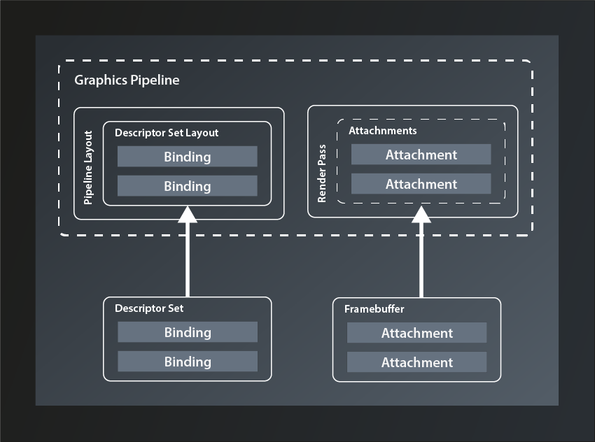
The RenderPass structure might be a bit confusing at first, not least because of its name, but it is actually not that difficult. A render pass describes where the pipeline stores the output it produces. Since that output is normally color and depth values for each fragment it seems logical that images are used as the storage structure. The render pass contains descriptions of those images and how to use them, those descriptions are called ‚attachments‘.

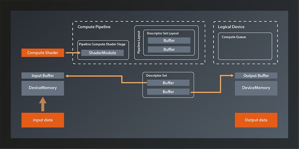
So conceptually the render pass is not that different from the pipeline layout. The attachments correspond to the descriptor bindings in that they are the logical representation of concrete data structures that will be bound to the pipeline when that is executed. The equivalent to the descriptor set is called ‚framebuffer‘ (because it stores the data for one rendered frame):

Comparison between the Pipeline Layout and Descriptor Set with Bindings and the Render Pass and Framebuffer with Attachments
Fig. 2: Pipeline Layout vs Render Pass

But why is the structure called ‚render pass‘ and not something like ‚output layout‘ or ‚target layout‘? My guess is that the name was chosen because a new framebuffer is bound to the attachments for every frame, i.e. for every pass of the render loop. I still think something like ‚RenderTargetLayout‘ or so would have been less confusing, all the more since the actual cycle of the pipeline to produce one frame is also typically referred to as a render pass.

Anyway, the data structure we need to describe a render pass looks like this:

struct RenderPassCreateInfo
{
    ...
    RenderPassCreateInfo& setFlags( RenderPassCreateFlags flags_ );
    RenderPassCreateInfo& setAttachments( const container_t< const AttachmentDescription >& attachments_ );
    RenderPassCreateInfo& setSubpasses( const container_t< const SubpassDescription >& subpasses_ );
    RenderPassCreateInfo& setDependencies( const container_t< const SubpassDependency >& dependencies_ );
    ...
};
  • there’s only one flag defined at this point which we don’t need, so once more we’re going to ignore that parameter.
  • as said, the attachments_ describe the target images that the pipeline will output to. We’ll look at them in more depth in a minute
  • in a simple application like ours, the pipeline only renders one scene in one go. Complex graphical applications like games on the other hand often compose the pictures that are shown on screen from multiple passes, e.g. to render a user interface on top of the 3D scene or to apply post-processing effects. Therefore a render pass is actually a collection of subpasses_, each of which can use a different selection of the attachments as their in- or output. So, even though we don’t need more than one pass, we’ll have to define that as a subpass to the render pass.
  • the subpass dependencies_ are used to inform Vulkan about subpasses that require the output of another subpass as their input. We obviously won’t need that yet.

With that knowledge under our belt, let’s first implement a stub function to create our render pass:

vk::UniqueRenderPass create_render_pass( const vk::Device& logicalDevice )
{
    const auto renderPassCreateInfo = vk::RenderPassCreateInfo{};
    return logicalDevice.createRenderPassUnique( renderPassCreateInfo );
}

… and pass the result to our pipeline creation:

// pipelines.cpp

vk::UniquePipeline create_graphics_pipeline(
    const vk::Device& logicalDevice,
    const vk::ShaderModule& vertexShader,
    const vk::ShaderModule& fragmentShader,
    const vk::RenderPass& renderPass,
    const vk::Extent2D& viewportExtent
)
{
    ...
    const auto pipelineCreateInfo = vk::GraphicsPipelineCreateInfo{}
        .setStages( shaderStageInfos )
        .setPVertexInputState( &vertexInputState )
        .setPInputAssemblyState( &inputAssemblyState )
        .setPViewportState( &viewportState )
        .setPRasterizationState( &rasterizationState )
        .setPMultisampleState( &multisampleState )
        .setPColorBlendState( &colorBlendState )
        .setLayout( *pipelineLayout )
        .setRenderPass( renderPass );
    ...
}
// main.cpp

int main()
{
    ...
    const auto renderPass = vcpp::create_render_pass( logicalDevice );

    const auto pipeline = create_graphics_pipeline(
        logicalDevice,
        *vertexShader,
        *fragmentShader,
        *renderPass,
        vk::Extent2D{ windowWidth, windowHeight } );
    ...
}

Running this version brings us down to two validation errors (and the exception) – we’re getting closer!

Attachments

So let’s actually configure our render pass and see what that gets us. The first thing we need to set are the attachments. We want to draw a simple triangle on screen for now, which means that we only need the color output of the pipeline (and not depth values or anything else). So we should probably create a color attachment and pass that to the configuration. All attachments are created with the same structure:

struct AttachmentDescription
{
    ...
    AttachmentDescription& setFlags( AttachmentDescriptionFlags flags_ );
    AttachmentDescription& setFormat( Format format_ );
    AttachmentDescription& setSamples( SampleCountFlagBits samples_ );
    AttachmentDescription& setLoadOp( AttachmentLoadOp loadOp_ );
    AttachmentDescription& setStoreOp( AttachmentStoreOp storeOp_ );
    AttachmentDescription& setStencilLoadOp( AttachmentLoadOp stencilLoadOp_ );
    AttachmentDescription& setStencilStoreOp( AttachmentStoreOp stencilStoreOp_ );
    AttachmentDescription& setInitialLayout( ImageLayout initialLayout_ );
    AttachmentDescription& setFinalLayout( ImageLayout finalLayout_ );
    ...
};
  • there is one possible flag defined, but that is only relevant for advanced use cases where multiple attachments share the same physical memory. We therefore once more ignore the flags_ parameter
  • the format_ specifies the color format of the attachment, i.e. the number of bits per color channel, how they are to be interpreted (e.g. signed vs unsigned) and the order of the channels.
  • the samples_ parameter defines the number of multisample fragments per pixel. Since we’re not using multisampling for now, we’ll set it to SampleCountFlagBits::e1
  • loadOp_ tells Vulkan what to do when loading the attachment at the beginning of the render cycle. The following options are available:
    • AttachmentLoadOp::eLoad: load the attachment and don’t touch the content. This is useful if you want to modify an already existing image by rendering into it
    • AttachmentLoadOp::eClear: set the whole attachment to the clear color initially. The clear color can be set at the beginning of the render cycle. Essentially you set a background color for your image with this option.
    • AttachmentLoadOp::eDontCare: allow Vulkan to do whatever it wants with the contents of the attachment. If you’re sure that you’ll render every single fragment in the image anyway, this is probably the most efficient option.
  • similarly, storeOp_ tells Vulkan what to do with the attachment at the end of the render cycle. The available options here are:
    • AttachmentStoreOp::eStore: this is the option you want to set if you intend to use the image after the render pass has ended, e.g. for displaying it on the screen.
    • AttachmentStoreOp::eDontCare: this tells Vulkan that you don’t need the attachment after the end of the render cycle, so it can do with it whatever it wants. This usually is the case for the depth values or for any intermediate images that are only needed during the render cycle.
  • stencilLoadOp_ and stencilStoreOp_ are essentially the same. They are only needed if the attachment is a combined depth-stencil attachment, in which case you can use different operations for the depth values (those are controlled by loadOp_ and storeOp_) and the stencil values.
  • initialLayout_ tells Vulkan what layout the respective image will have at the beginning of the render cycle, finalLayout_ is the layout that Vulkan should leave the attachment in at the end of the render cycle. We’ll talk more about image layouts at a later point, for now we’ll set our initial layout to eUndefined and the final layout to be optimized for use with a surface.

So let’s put that into practice and extend our create_render_pass function. Since we don’t want to be limited to a specific color format we’ll just pass that one in as a parameter.

vk::UniqueRenderPass create_render_pass(
    const vk::Device& logicalDevice,
    const vk::Format& colorFormat
)
{
    const auto colorAttachment = vk::AttachmentDescription{}
        .setFormat( colorFormat )
        .setSamples( vk::SampleCountFlagBits::e1 )
        .setLoadOp( vk::AttachmentLoadOp::eClear )
        .setStoreOp( vk::AttachmentStoreOp::eStore )
        .setStencilLoadOp( vk::AttachmentLoadOp::eDontCare )
        .setStencilStoreOp( vk::AttachmentStoreOp::eDontCare )
        .setInitialLayout( vk::ImageLayout::eUndefined )
        .setFinalLayout( vk::ImageLayout::ePresentSrcKHR );

    const auto renderPassCreateInfo = vk::RenderPassCreateInfo{}
        .setAttachments( colorAttachment );

    return logicalDevice.createRenderPassUnique( renderPassCreateInfo );
}

On the call site we set the format parameter to a default vk::Format for the time being:

const auto renderPass = vcpp::create_render_pass( logicalDevice, vk::Format{} );

This doesn’t yet change much because as described above, we need to define at least one subpass for our render pass.

Subpasses

To define a subpass we need the vk::SubpassDescription structure:

struct SubpassDescription
{
    ...
    SubpassDescription& setFlags( SubpassDescriptionFlags flags_ );
    SubpassDescription& setPipelineBindPoint( PipelineBindPoint pipelineBindPoint_ );
    SubpassDescription & setInputAttachments( const container_t< const AttachmentReference >& inputAttachments_ );
    SubpassDescription & setColorAttachments(const container_t< const AttachmentReference >& colorAttachments_ );
    SubpassDescription & setResolveAttachments(const container_t< const AttachmentReference >& resolveAttachments_ );
    SubpassDescription & setPDepthStencilAttachment( const AttachmentReference* pDepthStencilAttachment_ );
    SubpassDescription & setPreserveAttachments( const container_t< const uint32_t >& preserveAttachments_ );
    ...
};
  • there are actually a few flags_ that we could set, but none of them is relevant for us at this point
  • the pipelineBindPoint_ determines the part of the pipeline that this subpass will use. There’s only few choices: eGraphics, eCompute or eRaytracing. Obviously we want to use eGraphics.
  • inputAttachments_ are the attachments that this subpass needs as input, i.e. the ones that already contain valid data which it will use.
  • colorAttachments_ are the images that this subpass will write its color output to. It is in principle possible to use the same attachment for input and output in one subpass, but there are quite a few tricky details to that, so I’d recommend to not do it unless you’re sure you need to.
  • resolveAttachments_ are used when working with multisampling. They are the single-sample-per-pixel images that the multisampled color attachments will be downsampled to.
  • depthStencilAttachment_ is – surprise – the image that will receive the depth and stencil data. As you see there can only be one of those, but we don’t need one anyway for now.
  • preserveAttachments tells Vulkan explicitly to leave those attachments alone although the subpass doesn’t use them. This is needed if you have 3 or more subpasses and want to use an attachment that was rendered to in a subpass other than the previous one. Without referencing that attachment in the preserveAttachments_ field, Vulkan might assume that you’re done with it and apply some optimization that destroys its content. Since we only have one subpass we can leave this parameter alone for now.

So it looks like we only need one AttachmentReference for our color attachment. Defining an AttachmentReference is pretty simple for a change:

struct AttachmentReference
{
    ...
    AttachmentReference& setAttachment( uint32_t attachment_ );
    AttachmentReference& setLayout( ImageLayout layout_ );
    ...    
};
  • attachment_ is the index of the attachment in the attachments_ container in RenderPassCreateInfo (see above).
  • layout_ tells Vulkan which layout the subpass can expect the respective attachment to have. For our standard color attachment we’ll use eColorAttachmentOptimal.

And with all that information we can now finally complete the creation of our render pass:

vk::UniqueRenderPass create_render_pass(
    const vk::Device& logicalDevice,
    const vk::Format& colorFormat
)
{
    const auto colorAttachment = vk::AttachmentDescription{}
        .setFormat( colorFormat )
        .setSamples( vk::SampleCountFlagBits::e1 )
        .setLoadOp( vk::AttachmentLoadOp::eClear )
        .setStoreOp( vk::AttachmentStoreOp::eStore )
        .setStencilLoadOp( vk::AttachmentLoadOp::eDontCare )
        .setStencilStoreOp( vk::AttachmentStoreOp::eDontCare )
        .setInitialLayout( vk::ImageLayout::eUndefined )
        .setFinalLayout( vk::ImageLayout::ePresentSrcKHR );

    const auto colorAttachmentRef = vk::AttachmentReference{}
            .setAttachment( 0 )
            .setLayout( vk::ImageLayout::eColorAttachmentOptimal );

    const auto subpass = vk::SubpassDescription{}
        .setPipelineBindPoint( vk::PipelineBindPoint::eGraphics )
        .setColorAttachments( colorAttachmentRef );

    const auto renderPassCreateInfo = vk::RenderPassCreateInfo{}
        .setAttachments( colorAttachment )
        .setSubpasses( subpass );

    return logicalDevice.createRenderPassUnique( renderPassCreateInfo );
}

Compile and run this version – et voilà! We still get one validation error that informs us about the color format being invalid (which is not really surprising given the fact that we use a default constructed Format structure), but the exception is finally gone.

Color Format

So, let’s deal with that color format parameter. As mentioned above, the color format basically describes how the color information for each pixel is represented in memory. That is definitely good to know, but it doesn’t really help us decide which format we should use. And there are many possible formats.

Thinking about it, what we want to do with the rendered image is to display it on screen. Or, more precisely we want to display it in our window. So we probably want the color format to be compatible to the surface we created in lesson 13. Is there a way to find out which color format our surface expects?

Turns out there is:

class PhysicalDevice
{
    ...
    std::vector< SurfaceFormatKHR > getSurfaceFormatsKHR( SurfaceKHR surface, ... ) const;
    ...
};

So this one returns a vector of SurfaceFormatKHR which probably is not the same as a vk::Format. Let’s have a look:

struct SurfaceFormatKHR
{
    Format format;
    ColorSpaceKHR colorSpace;
};

Alright, seems like this is pretty straightforward, we just have to use the format property (we’ll talk about color spaces in a later lesson).

Which leaves the question which format we should select if the surface supports more than one format and so the vector has more than one entry. In a real world application you’d probably have to create a sort of heuristic to find the supported color format that best matches your use case. We’ll go with the simplest approach here and just use the first format available1:

const auto surfaceFormats = physicalDevice.getSurfaceFormatsKHR( *surface );
const auto renderPass = vcpp::create_render_pass( logicalDevice, surfaceFormats[0].format );

And now the last validation error is finally gone as well, so we have a correct and working program again. Problem is: we still don’t see anything on the screen. This is to be expected as we did not connect our pipeline to any output yet. That’s what we’re going to do next time but I’d say this lesson has been long enough.


  1. As said before: if you encounter problems with this simplistic approach, please let me know and I’ll extend the tutorial to make it work for you as well.

Lesson 16: Creating the Graphics Pipeline – Part 2

Version 1.1, updated 2022-07-18

We’re still in the process of filling the GraphicsPipelineCreateInfo structure with data to create our first pipeline, so without further ado let’s continue where we left off last time.

Viewport State

The next thing we need to set is the viewport state. Here’s the declaration:

struct PipelineViewportStateCreateInfo
{
    ...
    PipelineViewportStateCreateInfo & setFlags( PipelineViewportStateCreateFlags flags_ );
    PipelineViewportStateCreateInfo & setViewports( const container_t< const Viewport >& viewports_ );
    PipelineViewportStateCreateInfo & setScissors( const container_t< const Rect2D >& scissors_ );
    ...
};

The flags are once again reserved for future use and not used yet. Which leaves viewports and scissors and it seems we are actually able to set several of each.

Viewports are pretty straightforward, they just define the dimensions of the ‚window‘ through which we look at our 3D scene, its position in our application window and the depth range which we’re able to see (in normalized device coordinates):

struct Viewport
{
    ...
    Viewport& setX( float x_ );
    Viewport& setY( float y_ ); 
    Viewport& setWidth( float width_ );
    Viewport& setHeight( float height_ );
    Viewport& setMinDepth( float minDepth_ );
    Viewport& setMaxDepth( float maxDepth_ );
    ...
};

Usually you will just set x_ and y_ to 0, and width_ and height_ to the size of the application window. But it’s possible to specify other values to e.g. draw only in the lower right quarter and leave the rest of the window blank to be filled with other things. You could also stretch the output by scaling width and height with different factors.

The depth values specify the z-value range in which primitives need to fall so that they are rendered. Usually you’ll set this range to 0 and 1.0 to actually apply the clipping range defined in the perspective transformation1.

The scissor is somewhat similar in that you can specify a region of your output image that the drawing will be limited to. The difference to the viewport is that the whole rendered image will be drawn into the viewport, whereas the scissor can be used to cut out a subsection of the rendering. Usually you will want to set the scissor to the whole output window size as well.

Visualization showing the effects of viewport and scissor on how the rendered image is placed in the application window
Fig. 1: Viewport and Scissor

Which leaves the question why we should be able to set multiple viewports and scissors for our pipeline? The most obvious example I can think of is a CAD or 3D modeling application, where the same scene is shown from different angles and with different perspectives. In Vulkan you could render those with a single pipeline2. We’ll stick to one viewport in this tutorial.

Let’s put that into practice. We want our pipeline creation to be independent from any application-specific constants like the window size and therefore pass the desired viewport extent as a parameter:

vk::UniquePipeline create_graphics_pipeline(
    const vk::Device& logicalDevice,
    const vk::ShaderModule& vertexShader,
    const vk::ShaderModule& fragmentShader,
    const vk::Extent2D& viewportExtent
)
{
    ...

    const auto viewport = vk::Viewport{}
        .setX( 0.f )
        .setY( 0.f )
        .setWidth( static_cast< float>( viewportExtent.width ) )
        .setHeight( static_cast< float>( viewportExtent.height ) )
        .setMinDepth( 0.f )
        .setMaxDepth( 1.f );

    const auto scissor = vk::Rect2D{ { 0, 0 }, viewportExtent };

    const auto viewportState = vk::PipelineViewportStateCreateInfo{}
        .setViewports( viewport )
        .setScissors( scissor );

    const auto pipelineCreateInfo = vk::GraphicsPipelineCreateInfo{}
        .setStages( shaderStageInfos )
        .setPVertexInputState( &vertexInputState )
        .setPInputAssemblyState( &inputAssemblyState )
        .setPViewportState( &viewportState );
    ...
}

… and modify our main function like so:

int main()
{
    constexpr int windowWidth = 800;
    constexpr int windowHeight = 600;

    try
    {
        const auto glfw = vcpp::glfw_instance{};
        const auto window = vcpp::create_window( windowWidth, windowHeight, "Vulkan C++ Tutorial" );

        ...

        const auto pipeline = create_graphics_pipeline(
            logicalDevice,
            *vertexShader,
            *fragmentShader,
            vk::Extent2D{ windowWidth, windowHeight } );
        ...
}
Rasterization State

Next in line is the rasterization state. Here’s the interface:

struct PipelineRasterizationStateCreateInfo
{
    ...
    PipelineRasterizationStateCreateInfo& setFlags( PipelineRasterizationStateCreateFlags flags_ );
    PipelineRasterizationStateCreateInfo& setDepthClampEnable( Bool32 depthClampEnable_ );
    PipelineRasterizationStateCreateInfo& setRasterizerDiscardEnable( Bool32 rasterizerDiscardEnable_ );
    PipelineRasterizationStateCreateInfo& setPolygonMode( PolygonMode polygonMode_ );
    PipelineRasterizationStateCreateInfo& setCullMode( CullModeFlags cullMode_ );
    PipelineRasterizationStateCreateInfo& setFrontFace( FrontFace frontFace_ );
    PipelineRasterizationStateCreateInfo& setDepthBiasEnable( Bool32 depthBiasEnable_ );
    PipelineRasterizationStateCreateInfo& setDepthBiasConstantFactor( float depthBiasConstantFactor_ );
    PipelineRasterizationStateCreateInfo& setDepthBiasClamp( float depthBiasClamp_ );
    PipelineRasterizationStateCreateInfo& setDepthBiasSlopeFactor( float depthBiasSlopeFactor_ );
    PipelineRasterizationStateCreateInfo& setLineWidth( float lineWidth_ );
    ...
};

Okay, so there’s actually quite a number of parameters to configure this stage. Let’s have a closer look:

  • the flags_ are once more reserved for future use and therefore not relevant for us
  • depthClampEnable_ controls whether calculated depth values are clamped to the viewport’s min and max depth values. Enabling this can avoid ‚holes‘ in your rendered geometry that result from fragments being discarded because their depth values are outside of the clipping range.
  • rasterizerDiscardEnable_ can be used to turn off the whole rasterization stage (and all subsequent stages with it). This might be useful if you want to use the results of the calculations in preceding shader stages for something else than drawing.
  • setPolygonMode controls whether Vulkan will draw only points, lines or filled primitives. This is not the same as the topology from the input assembly stage: that one controlled how the vertices are to be combined to shapes while the polygonMode_ here only changes how the resulting geometry is rasterized.
  • setCullMode and setFrontFace control the back face culling optimization’s behaviour. We’ll get to that eventually, but for now let’s just leave the parameters at their defaults.
  • the depth bias functions are related to a more advanced technique that helps prevent rendering errors which are caused by rounding effects when calculating the depth values of different primitives. We won’t need that for our single triangle either.
  • the lineWidth_ is only relevant when rasterizing in the polygon mode vk::PolygonMode::eLines. Which means we don’t really need that, however we’re still required to set it and the validation will yell at us if we set anything but 1.0.

So, it turns out that it’s actually not that complicated to set the rasterization parameters for our use case:

const auto rasterizationState = vk::PipelineRasterizationStateCreateInfo{}
    .setDepthClampEnable( false )
    .setRasterizerDiscardEnable( false )
    .setPolygonMode( vk::PolygonMode::eFill )
    .setLineWidth( 1.f );

If you run this version you might spot that one of the error messages has changed and is now complaining about the multisample state missing. That one’s next on our list so let’s get right to it.

Multisampling

As I mentioned in lesson 14 we won’t be using multisampling for now, but Vulkan requires us to configure it anyway. Luckily we can just use a default-constructed PipelineMultisampleStateCreateInfo:

vk::UniquePipeline create_graphics_pipeline(
    const vk::Device& logicalDevice,
    const vk::ShaderModule& vertexShader,
    const vk::ShaderModule& fragmentShader,
    const vk::Extent2D& viewportExtent
)
{
    ...

    const auto multisampleState = vk::PipelineMultisampleStateCreateInfo{};

    const auto pipelineCreateInfo = vk::GraphicsPipelineCreateInfo{}
        .setStages( shaderStageInfos )
        .setPVertexInputState( &vertexInputState )
        .setPInputAssemblyState( &inputAssemblyState )
        .setPViewportState( &viewportState )
        .setPRasterizationState( &rasterizationState )
        .setPMultisampleState( &multisampleState );
    ...
}

And with that we’re yet another error down. Yay!

As mentioned before, we’ll not be using the depth stencil state for now since we will only draw one triangle in the beginning. And in this case we also don’t need to do anything to satisfy Vulkan, so let’s move on to the color blending configuration.

Color Blending

Color blending is what happens after the graphics pipeline has determined the color of a fragment and updates the corresponding framebuffer image accordingly. In the simplest case the new color just replaces whatever color was stored in that location before. This is the behavior when blending is disabled and this is what we want to do for now. Nevertheless, Vulkan requires us to be explicit here again and provide a PipelineColorBlendStateCreateInfo.

A framebuffer may contain multiple destination images (so-called color attachments) and Vulkan allows us to set individual color blending modes for each one. Therefore the create info is basically a collection of PipelineColorBlendAttachmentState structures:

struct PipelineColorBlendStateCreateInfo
{
    ...
    PipelineColorBlendStateCreateInfo& setAttachments( const container_t< const vk::PipelineColorBlendAttachmentState >& attachments_ );    
    ...
}

This time we also don’t get away with simply using a default constructed PipelineColorBlendAttachmentState. Instead we need to disable color blending explicitly but still instruct Vulkan which color channels we want to write:

struct PipelineColorBlendAttachmentState
{
    ...
    PipelineColorBlendAttachmentState& setBlendEnable( Bool32 blendEnable_ );
    PipelineColorBlendAttachmentState& setColorWriteMask( ColorComponentFlags colorWriteMask_ );
    ...
};

So here’s how we configure our color blend state:

const auto colorBlendAttachment = vk::PipelineColorBlendAttachmentState{}
    .setBlendEnable( false )
    .setColorWriteMask(
        vk::ColorComponentFlagBits::eR |
        vk::ColorComponentFlagBits::eG |
        vk::ColorComponentFlagBits::eB |
        vk::ColorComponentFlagBits::eA );

const auto colorBlendState = vk::PipelineColorBlendStateCreateInfo{}
    .setAttachments( colorBlendAttachment );

Running this version you’ll still get the validation errors and the crash. Nevertheless we’re slowly making progress and I want to stop it here for today. I know that this is annoying, after all it’s the second lesson in a row after which our code doesn’t really work. Please be patient my friends, we’ll soon be over the hump and start to have real fun.


  1. Perspective transformation is essentially the virtual camera with which you look at the scene and usually happens in the vertex shader. Mathematically speaking it transforms the coordinates of each vertex from the view space to a normalized space, i.e. the output coordinates are in the range -1…1 for x and y and 0…1 for z. We’ll get into more details in a later session.
  2. Note that multi-viewport support is not mandatory to be implemented in your graphics driver, so you need to check the maxViewports member of the PhysicalDeviceLimits described in lesson 3 if you want to make use of that feature.

Lesson 15: Creating the Graphics Pipeline – Part 1

Version 1.0, updated 2022-06-03

Alright, our task for today is to start filling the GraphicsPipelineCreateInfo structure with information on how we want our graphics pipeline to be configured. So let’s dive straight in:

Setting up the pipeline stages

As mentioned in the last lesson, we can ignore the flags, so let’s start with the setStages function. That one takes a container of PipelineShaderStageCreateInfo, which we already looked at back in lesson 8. The difference is that now we need at least a vertex and a fragment shader, so let’s prepare our pipeline creation for that:

vk::UniquePipeline create_graphics_pipeline(
    const vk::Device& logicalDevice,
    const vk::ShaderModule& vertexShader,
    const vk::ShaderModule& fragmentShader
)
{
    const auto shaderStageInfos = std::vector< vk::PipelineShaderStageCreateInfo >{
        vk::PipelineShaderStageCreateInfo{}
            .setStage( vk::ShaderStageFlagBits::eVertex )
            .setPName( "main" )
            .setModule( vertexShader ),
        vk::PipelineShaderStageCreateInfo{}
            .setStage( vk::ShaderStageFlagBits::eFragment )
            .setPName( "main" )
            .setModule( fragmentShader ),
    };

    const auto pipelineCreateInfo = vk::GraphicsPipelineCreateInfo{}
        .setStages( shaderStageInfos );

    return logicalDevice.createGraphicsPipelineUnique( vk::PipelineCache{}, pipelineCreateInfo ).value;
}

So far, so good. We don’t have those shaders yet though. Let’s change that.

Vertex and fragment shader

We already know how to write a shader in principle, so let’s get going right away. For the vertex shader I’ll take a page from the original Vulkan Tutorial’s book here and put all the vertex information into the shader initially. We’ll have to change this later, but right now it will simplify things because it means the shader doesn’t need any input:

#version 450

vec4 positions[3] = vec4[](
    vec4(0.0, -0.5, 0.0, 1.0 ),
    vec4(0.5, 0.5, 0.0, 1.0 ),
    vec4(-0.5, 0.5, 0.0, 1.0 )
);

You might wonder why I use 4-dimensional vectors here to define positions in a 3D space. The answer is that the 4th component (the w-component) facilitates some important mathematical operations that we will want to perform on these coordinates at some point, e.g. transformations and perspective. We’ll get into more detail later, as you can see we just set the 4th component to 1 for now.

So we have the coordinates for one triangle defined. These coordinates are already in normalized world space, therefore all we need to do now is tell the shader to output those coordinates to the next stage. Because the main responsibility of a vertex shader is so clearly defined, GLSL actually provides a builtin variable to assign the shader result to: gl_Position, which is also a 4-dimensional vector. The only problem is that this only takes one position at a time, as the shader is supposed to process individual vertices. But GLSL has us covered here as well, as there is an internal property that tells us the index of the vertex we’re currently processing:

void main()
{
    gl_Position = positions[gl_VertexIndex];
}

That’s already it for our minimal vertex shader. Let’s save it in our shaders directory and modify the CMake file to compile that one instead of the compute shader:

add_custom_target( vertex_shader
    COMMAND             "glslc" "${VULKAN_TUTORIAL_PROJECT_ROOT}/shaders/vertex.vert" -o "shaders/vertex.spv"
    WORKING_DIRECTORY   "${CMAKE_BINARY_DIR}/bin"
)

We also need to change the dependency for our project accordingly:

add_dependencies( ${PROJECT_NAME} vertex_shader )

Running CMake and building your project should now compile the vertex shader without errors (there will of course be compile errors in main.cpp because we modified the function signature of create_graphics_pipeline)

Let’s move on to the fragment shader now. The first step is to specify the output of the shader:

#version 450

layout(location = 0) out vec4 outColor;

You might wonder why we need to do that. Isn’t there a builtin variable similar to gl_Position that takes in the fragment shader output? No there isn’t, and for good reason: in a simple graphics pipeline like the one we’re going to create at first, the output is indeed always a single 32-bit color value. But there are applications where you might want a different color format. Or, in more complex scenarios, you might want to output to multiple targets at the same time (e.g. not only a color value but also the depth value or texture coordinate for the respective fragment). Bottom line: to enable this kind of flexibility, Vulkan can not make any assumptions about the output of the fragment shader.

Alright, so now we need to fill that output color we defined with a value. We’ll again choose the simplest path for now and just always output a pure red:

void main() 
{
    outColor = vec4(1.0, 0.0, 0.0, 1.0);
}

Add the shader to your CMake file in the same way as we did for the vertex shader and compile your project. It should work as before, only that the compiled fragment shader is now showing up in your output directory.

Alright, now we can load the shaders into our application and pass them to our pipeline creation function. This is trivial since we’ve already created the necessary loader function back in lesson 7:

const auto vertexShader = create_shader_module( logicalDevice, "./shaders/vertex.spv" );
const auto fragmentShader = create_shader_module( logicalDevice, "./shaders/fragment.spv" );

const auto pipeline = create_graphics_pipeline( 
    logicalDevice,
    *vertexShader,
    *fragmentShader );

Okay, we’ve completed the first step. If you run the program now and watch closely you will find that the first validation error has gone (the others and the exception are still there though). Looks like we’re one step closer to a working pipeline, yay!

Vertex input and input assembly state

One additional (temporary) advantage of defining the vertices in the shader is that we can pretty much ignore the PipelineVertexInputStateCreateInfo parameter because we don’t pass in any vertices yet. Vulkan requires us to set this parameter though, so we’ll have to give it the pointer to a default constructed instance.

Next thing we want to set is the pInputAssemblyState_. As described last time, this stage essentially prepares the input for the vertex shader stage. It’s a fixed stage and we actually cannot control that many parameters for it:

struct PipelineInputAssemblyStateCreateInfo
{
    ...
    PipelineInputAssemblyStateCreateInfo& setFlags( PipelineInputAssemblyStateCreateFlags flags_ );
    PipelineInputAssemblyStateCreateInfo& setTopology( PrimitiveTopology topology_ );
    PipelineInputAssemblyStateCreateInfo& setPrimitiveRestartEnable( Bool32 primitiveRestartEnable_ );
    ...
};
  • The flags_ are once more only reserved for future use.
  • The topology_ defines how to combine the vertices to primitives, i.e. to geometric shapes to be drawn. The possible values include:
    • ePointList if you want to draw single points
    • eTriangleList if you want to draw draw individual triangles
    • eTriangleStrip if you want to draw a series of triangles where every triangle shares two vertices with the previous one
    • eTriangleFan if you want to draw a series of triangles that all share one vertex
    • … and several more
  • primitiveRestartEnable_ is only relevant when doing indexed drawing, something we’ll look into later. At this point we just ignore it.

Since we are only drawing a single triangle for now, it doesn’t really matter which of the eTriangle... topologies we set, eTriangleList seems like the most generic so let’s just use that one.

And with that our pipeline creation function looks like that now:

vk::UniquePipeline create_graphics_pipeline(
    const vk::Device& logicalDevice,
    const vk::ShaderModule& vertexShader,
    const vk::ShaderModule& fragmentShader
)
{
    const auto shaderStageInfos = std::vector< vk::PipelineShaderStageCreateInfo >{
        vk::PipelineShaderStageCreateInfo{}
            .setStage( vk::ShaderStageFlagBits::eVertex )
            .setPName( "main" )
            .setModule( vertexShader ),
        vk::PipelineShaderStageCreateInfo{}
            .setStage( vk::ShaderStageFlagBits::eFragment )
            .setPName( "main" )
            .setModule( fragmentShader ),
    };

    const auto vertexInputState = vk::PipelineVertexInputStateCreateInfo{};
    const auto inputAssemblyState = vk::PipelineInputAssemblyStateCreateInfo{}
        .setTopology( vk::PrimitiveTopology::eTriangleList );
    
    const auto pipelineCreateInfo = vk::GraphicsPipelineCreateInfo{}
        .setStages( shaderStageInfos )
        .setPVertexInputState( &vertexInputState )
        .setPInputAssemblyState( &inputAssemblyState );

    return logicalDevice.createGraphicsPipelineUnique( vk::PipelineCache{}, pipelineCreateInfo ).value;
}

If you compile and run this version, you’ll still get the validation warnings and the crash, which tells us that we’re by far not done yet. Nevertheless I want to end here for today and continue next time.

Lesson 14: The Graphics Pipeline

Version 1.2, updated 2022-06-01

So, now that we have our window and the associated surface ready, let’s get started implementing our graphics pipeline. Obviously, to be able to do that, it might help to understand how a graphics pipeline actually works.

The logical graphics pipeline

Like the compute pipeline, the graphics pipeline takes some input data, processes it and outputs the result. The key difference is that while a compute pipeline is pretty much ‚general purpose‘, the graphics pipeline is tailored to a very specific use case: to transform a 3D world that is made of thousands of primitives (usually triangles) into a 2D image of that world. Where the compute pipeline only has one processing stage that is freely programmable, a graphics pipeline has at least five stages with clearly defined responsibilities. Some of those stages are fixed in their functionality, the behaviour of others is controlled by a shader program that we provide (like the compute shader). Each stage takes the output of the previous one as its input – hence the name pipeline.

So let’s look at the logical structure of a Vulkan graphics pipeline:

Vulkan C++ Tutorial: Diagram of the different stages in a Vulkan graphics pipeline and the data flow through the pipeline
Fig. 1: The logical structure of the graphics pipeline as we will create it

The main input to the graphics pipeline is a collection of so-called vertices1 that are stored in a specific type of buffer. Technically speaking, a vertex is just a tuple of values that don’t have any predefined meaning. In practice however it is almost always the coordinates of a point in 3D space plus associated attributes such as e.g. it’s color, the corresponding texture index and so on. These vertices are the corners of all the primitives that make up the 3D world we want to render.

The first stage of the pipeline itself is the Input Assembly Stage. This is a fixed stage whose main responsibility is to collect the vertex input data from the specified buffer(s) and to ensure that the right vertices in the right order are passed on to the vertex shader stage. This enables e.g. re-using vertices that are shared between multiple primitives and thus saving memory bandwidth.

Next in line is the Vertex Shader Stage. This is one of the programmable stages, and it’s the only one that is mandatory to be specified. So we are always required to write a vertex shader. This shader’s main responsibility is to transform one input vertex coordinate to an output coordinate so that it ends up in the right position in our 3D world, relative to the location of our virtual camera. We’ll talk about this process in more detail later in this series. The vertex shader may also perform additional tasks like e.g. per-vertex lighting calculations.

Tesselation and Geometry Stage are also programmable, but they are optional and we won’t be using them for now. I therefore won’t go into details here. Suffice it to say that they can be used to let the GPU create additional vertices to add geometry to the scene and improve the level of detail.

The Primitive Assembly is a fixed stage that takes the processed (and – if we have tesselation and / or geometry shaders – generated ) vertices and groups them into primitives by using the information from the input assembly stage. Without this step, the next stage would not be able to do its job as it would still only see individual vertices and couldn’t process primitives as a whole. The primitive assembly stage is also the one that applies the viewport transformation, i.e. it transforms vertices from normalized 3D device coordinates into 2D image coordinates.

Rasterization is another fixed stage whose main job it is to transform the logical representation of a primitive (up to now those are still defined by their vertices) into a collection of so-called fragments that are interpolated between the vertices and make up the actual visual shape on your screen2. The rasterization stage is also responsible for operations like back-face culling and depth clamping (more on those later), and to determine whether the geometry ultimately is drawn as points, lines or filled shapes.

Each fragment is then sent to the next stage: the Fragment Shader. This is a programmable stage that is run once per fragment3, usually primarily to determine its color as a result of lighting and surface properties. Depth testing and multisampling – if enabled – also happen in the context of the fragment shader stage. It is actually not mandatory to provide a shader for this stage and there are use cases where it makes sense to omit that4. We want to generate output on the screen however, so we will write a fragment shader.

And finally the Color Blending Stage. This is where the color of each new fragment is merged with the already existing color value at the respective location. Depending on the configuration of this stage, this allows for hardware-accelerated transparency, translucency etc.

The output data of the graphics pipeline is stored in a so called framebuffer. In the simplest case the output is just one rendered image, but the framebuffer can hold multiple of those, e.g. for also storing the depth values for each fragment. This is why the fragment shader stage and the color blending stage have to interact with the framebuffer instead of just writing to it.

Creating the graphics pipeline

Okay, so much for the theory. Let’s look at how we can create a graphics pipeline in practice. We’ve actually already had a brief look at the needed function back in lesson 8:

class Device
{
    ...
    // return values are actually ResultValue< UniquePipeline >, see chapter 2
    UniquePipeline createGraphicsPipelineUnique( PipelineCache pipelineCache, const GraphicsPipelineCreateInfo& createInfo, ... );  
    ...
};

So the only difference compared to creating a compute pipeline is that this time we need a GraphicsPipelineCreateInfo. So let’s have a look at that one:

struct GraphicsPipelineCreateInfo
{
    ...
    GraphicsPipelineCreateInfo& setFlags( PipelineCreateFlags flags_ ) 
    GraphicsPipelineCreateInfo& setStages( const container_t< const PipelineShaderStageCreateInfo >& stages_ );
    GraphicsPipelineCreateInfo& setPVertexInputState( const PipelineVertexInputStateCreateInfo* pVertexInputState_ );
    GraphicsPipelineCreateInfo& setPInputAssemblyState( const PipelineInputAssemblyStateCreateInfo* pInputAssemblyState_ );
    GraphicsPipelineCreateInfo& setPTessellationState( const PipelineTessellationStateCreateInfo* pTesselationState_ );
    GraphicsPipelineCreateInfo& setPViewportState( const PipelineViewportStateCreateInfo* pViewportState_ ) 
    GraphicsPipelineCreateInfo& setPRasterizationState( const PipelineRasterizationStateCreateInfo* pRasterizationState_ );
    GraphicsPipelineCreateInfo& setPMultisampleState( const PipelineMultisampleStateCreateInfo* pMultisampleState_ );
    GraphicsPipelineCreateInfo& setPDepthStencilState( const PipelineDepthStencilStateCreateInfo* pDepthStencilState_ );
    GraphicsPipelineCreateInfo& setPColorBlendState( const PipelineColorBlendStateCreateInfo* pColorBlendState_ );
    GraphicsPipelineCreateInfo& setPDynamicState( const PipelineDynamicStateCreateInfo* pDynamicState_ );
    GraphicsPipelineCreateInfo& setLayout( PipelineLayout layout_ );
    GraphicsPipelineCreateInfo& setRenderPass( RenderPass renderPass_ );
    GraphicsPipelineCreateInfo& setSubpass( uint32_t subpass_ );
    GraphicsPipelineCreateInfo& setBasePipelineHandle( Pipeline basePipelineHandle_ );
    GraphicsPipelineCreateInfo& setBasePipelineIndex( int32_t basePipelineIndex_ );
    ...
};

At first sight that seems quite a lot of stuff to configure. But compare this interface to the logical structure I described above – a lot of this should already bear some meaning for you by now. Anyway, let’s go through the functions one by one quickly (we’ll cover the relevant ones in more detail later):

  • there are several PipelineCreateFlags that we could set (quite many actually since Vulkan version 1.1), but since none of them is relevant for us at this point we once more leave the flags alone
  • this time we can set multiple stages_, not just one as for the compute pipeline. And that makes sense, as we just learned that there are the vertex, geometry, tesselation and fragment shader stages that we can define for a graphics pipeline.
  • setPVertexInputState, as it’s name suggests, describes the vertex input to the pipeline, i.e. where to find and how to interpret the vertex data. I didn’t list this as a separate stage in the overview above because to my knowledge there is no actual functionality associated with the vertex input state. It’s really just a bit of information that we need to pass to the pipeline.
  • pInputAssemblyState_ unsurprisingly determines the behavior of the input assembly stage
  • since we won’t use tesselation, setPTesselationState is not of any interest for us right now
  • pViewportState specifies the configurable part of the primitive assembly stage. As described above, this is controlling how 3D world coordinates are converted into 2D framebuffer coordinates.
  • pRasterizationState_ is hopefully self-explanatory again
  • multisampling is a technique to improve the visual quality, especially of edges, by computing multiple fragments per screen pixel and then outputting an average. We won’t be using this feature until later in this series, however, Vulkan requires us to define and set a pMultisampleState_.
  • we also won’t need pDepthStencilState_ for now as we’re only going to draw a single triangle initially and therefore don’t have to deal with depth testing yet
  • pColorBlendState_ is important again but should be conceptually clear as well
  • in general pipelines in Vulkan are fixed, which means that you cannot change them after creation. That has a lot of advantages for the drivers ability to optimize the pipeline performance. But the flip-side of that is that you have to re-create the pipeline every time parts of the configuration change. That would be very wasteful in a scenario where such changes happen frequently. Therefore Vulkan allows you to mark parts of the pipeline as dynamic upfront, so that you can apply changes without having to recreate the whole pipeline. Our pipeline will not be changing, so we will ignore setPDynamicState
  • You may remember that we had to create a PipelineLayout for our compute pipeline, and that this was used to set up the descriptors. We will start out without specifying any data input to the pipeline, so we can just use an empty layout for now.
  • the RenderPass is difficult to explain in a few words. We’ll look at this one in more depth when we actually get to creating one. For now suffice it to say that a render pass describes the target structures the pipeline renders to
  • and finally there’s the two functions relating to the base pipeline. Those become relevant when you derive similar pipelines from a common base pipeline in order to be able to switch among them rapidly. We won’t be using this feature either.

Alright, we now have an overview on what we need to do to create a render pipeline. Let’s finish today’s lesson by preparing the corresponding function:

vk::UniquePipeline create_graphics_pipeline( const vk::Device& logicalDevice )
{
    const auto pipelineCreateInfo = vk::GraphicsPipelineCreateInfo{};

    return logicalDevice.createGraphicsPipelineUnique( 
        vk::PipelineCache{}, 
        pipelineCreateInfo ).value;
}

And to check whether that function is actually working, let’s already call it from main:

int main()
{
    try
    {
        ...

        const auto pipeline = create_graphics_pipeline( logicalDevice );

        while ( !glfwWindowShouldClose( window.get() ) )
        {
            glfwPollEvents();
        }
    }
    catch( const std::exception& e )
    {
        std::cout << "Exception thrown: " << e.what() << "\n";
        return -1;
    }
    return 0;
}

If you compile and run this now, you’ll get a lot of validation errors and an exception. This is okay for now because our pipelineCreateInfo doesn’t really contain any information yet and so Vulkan doesn’t know what to do. Starting next time we’ll fill the create info with the proper data.


  1. In reality there usually is also other input like vertex indices, global variables (aka uniforms) etc. They are not relevant for understanding the basic principles of the pipeline though, therefore I’m ignoring them at this point.
  2. A fragment is basically a position in the 2D space of the framebuffer with an associated a depth value, plus potentially some interpolated data from previous stages. For simplicity you can think of the fragments as the pixels of the image that are finally drawn on the screen, although this is not really accurate as there is not always a 1:1 equivalence between a fragment and a pixel (e.g. in the presence of multisampling).
  3. It’s good to keep in mind that the fragment shader, since it is run a lot more often than the other shaders, has a significant impact on the overall processing time of the pipeline.
  4. This makes sense e.g. when you’re only interested in the depth value of a fragment because you’re doing shadow mapping or a related technique
Further Reading

Lesson 13: Creating the Application Window

Version 1.1, updated 2022-06-22

Alright, the time has finally come to look into the specifics of graphics programming with Vulkan, so let’s dive straight in.

Our logical device creation function is still hardwired to create a compute queue. We need graphics capabilities now, so we want to be able to reconfigure that. Thanks to our utility function get_queue_index the necessary modification is very straightforward:

logical_device create_logical_device( 
    const vk::PhysicalDevice& physicalDevice,
    const vk::QueueFlags requiredFlags
)
{
    ...
    const auto queueFamilyIndex = get_suitable_queue_family(
        queueFamilies,
        requiredFlags
    );
    ...
}

With this change in place we can now create our logical device like this:

int main()
{
    ...
    const auto logicalDevice = vcpp::create_logical_device( 
        physicalDevice,
        vk::QueueFlagBits::eGraphics );
    ...
}
GLFW

So far so good. The next thing we need for graphics programming is a window1. After all, we’d like to be able to see what we’re programming, right? Now, window handling is a whole universe of its own. Moreover, although the concepts are very similar across all platforms, the details and concrete implementation are completely platform specific. Vulkan was designed to be a platform agnostic API, so it doesn’t meddle with that stuff at all2. Luckily we still don’t have to implement the window support ourselves because other people have done that work for us already. We’ll use the GLFW library, which is a sort of quasi-standard for that purpose.

We’re also going to use the format libary for string manipulation. It is part of the C++ standard library since C++20, but since we’re still using the older C++17 standard here, we have to use it’s open source predecessor.

To add those libraries to our project we need to add them to our conanfile.txt:

[requires]
    glfw/[>3.3.6]
    fmt/[>8.0.0]
    ...

Then, from within your build folder, run > conan install and rebuild your CMake project to make sure everything works as before.

In the last lesson we invested all that effort to clean up our codebase, so let’s stick to the good habits from now on and try to avoid cluttering main.cpp. We’ll have quite a bit of code relating to GLFW, therefore I suggest to create a new source code file pair glfw_utils (don’t forget to add the files to the CMakeLists.txt).

Before we can do anything useful with it we need to initialize the library. GLFW offers the function int glfwInit() for that purpose, which seems reasonable enough. Unfortunately, as a well behaved program, we are also supposed to call the corresponding glfwTerminate() function when we’re done using GLFW. As C++ programmers we tend to dislike this pattern and would much rather use RAII in such cases. So let’s do exactly that and wrap the calls in a wrapper class3:

#define GLFW_INCLUDE_VULKAN
#include <GLFW/glfw3.h>

namespace vcpp
{
    class glfw_instance
    {
    public:

        glfw_instance();
        ~glfw_instance();

        glfw_instance( const glfw_instance& ) = delete;
        glfw_instance( glfw_instance&& ) = delete;

        glfw_instance& operator= ( const glfw_instance& ) = delete;
        glfw_instance& operator= ( glfw_instance&& ) = delete;
    };
}

GLFW was originally written for OpenGL (hence the name). Therefore we need to define GLFW_INCLUDE_VULKAN to make it work with Vulkan as well. I’ve deleted the copy constructors and assignment operators for our class to make sure we don’t accidentally terminate GLFW by creating another instance of our class. The corresponding implementation in the .cpp file looks like this:

namespace vcpp
{
    glfw_instance::glfw_instance()
    {
        if ( auto result = glfwInit(); result != GLFW_TRUE )
            throw std::runtime_error( fmt::format( "Could not init glfw. Error {}", result ) );
    }

    glfw_instance::~glfw_instance() { glfwTerminate(); }
}

Using GLFW correctly is now a simple one-liner (not counting the necessary #include):

const auto glfw = vcpp::glfw_instance{};
Creating the Window

Now we’d like to have a window. Again GLFW uses the default C pattern by providing the functions glfwCreateWindow and glfwDestroyWindow. And again, we’d like to be able to package that into an RAII pattern. This time, because glfwCreateWindow returns a pointer to the created window, we can make use of C++‘ unique_ptr:

using window_ptr_t = std::unique_ptr< GLFWwindow, decltype( &glfwDestroyWindow ) >;

Since the call for creating the window pointer is not very concise, and since we’ll probably want to set some properties for the window in the future, we’ll put the window creation into a utility function again:

window_ptr_t create_window( int width, int height, const std::string& title )
{
    return window_ptr_t{ 
        glfwCreateWindow( width, height, title.c_str(), nullptr, nullptr ),
        glfwDestroyWindow
    };
}

And now we can again create the window with one simple call:

int main()
{
    try
    {
        const auto glfw = vcpp::glfw_instance{};
        const auto window = vcpp::create_window( 800, 600, "Vulkan C++ Tutorial" );
    ...

If you run the program now, you’ll probably see a window flashing up for a moment and then vanishing again. That’s perfectly correct – our program executes its main function and when it reaches the end of that it terminates and thus destroys the window. Obviously this is not how we want our application to behave though. We would like the application to run and the window to stay open until we close it explicitly. That’s where the ‚run loop‘ or ‚event loop‘ comes into play. I’m not going to go into any details about that in this tutorial, it would blow up the scope way too much. Suffice it to say that the run loop is essentially just a normal loop which in every cycle checks for OS events (such as mouse events or key strokes) and processes them. If the user or the operating system tell the application to terminate, the loop is exited. For GLFW a very basic run loop looks like this:

while ( !glfwWindowShouldClose( window.get() ) )
{
    glfwPollEvents();
}

So in every iteration of the loop we let GLFW poll for new operating system events. We don’t do anything explicit with them yet, but calling the poll function enables GLFW to do some magic under the hood (without that, the call to glfwWindowshouldClose wouldn’t work correctly and we couldn’t exit the application by closing the window). Compile and run the program now and you will see that we get a window that behaves exactly as we wanted it to.

Alright, we have our window, now we’d like to draw to it. The trouble is: since the Vulkan core itself has no idea about windows, it also doesn’t know how to render into one. So what do we do?

Window System Integration and Surfaces

Well, the creators of Vulkan obviously knew that presentation (i.e. rendering to a screen or window) would be a very common requirement, so they took care that this problem be solved. The solution they came up with is to have the presentation support be implemented in instance extensions which are commonly referred to as the ‚Windows System Integration (WSI)‘ extensions. There is a platform-independent ‚VK_KHR_surface‘ extension which defines a generic interface for a concept called ’surface‘. You can think of a surface as a sort of a canvas that Vulkan can render to. The actual implementation of the surface is then provided by additional platform-specific extensions. So the whole thing works pretty much the same as abstract base classes and derived implementation classes in C++. Vulkan can use the abstract interface and the platform-specific implementation takes care of the actual presentation.

If you want to verify that you have the surface extensions installed take a look at the instance extensions that our application prints out. You should find VK_KHR_surface among the names, along with a few other surface-related extensions.

For us this means that if we want to render to our window we need to enable those extensions. To do that we could now simply add the respective extension names to our extensionsToEnable vector in create_instance. The problem with that however is that some of the required extensions are obviously platform specific. So we’d need to use preprocessor #defines or something similar to keep our application platform agnostic. Luckily there is an easier way because GLFW already has a function that tells us which extensions we need to enable on the current system:

const char** glfwGetRequiredInstanceExtensions( uint32_t* count );

This one returns a C-array of C-Strings with the names of the required extensions. The size of that array is returned in the output parameter count. Since I want to keep all GLFW code in glfw_utils, I’ll add a function to wrap that call4:

std::vector< std::string > get_required_extensions_for_glfw()
{
    std::vector< std::string > result;
    std::uint32_t glfwExtensionCount = 0;
    const char** glfwExtensions = glfwGetRequiredInstanceExtensions( &glfwExtensionCount );
    for( std::uint32_t i = 0; i < glfwExtensionCount; ++i )
        result.push_back( glfwExtensions[i] );
    return result;
}

We could now call this function from inside create_instance directly and add the extensions to our vector of extensions to enable. That would create a tight coupling between glfw_utils and devices though, therefore I’ll go with a different approach and change create_instance as follows:

vk::UniqueInstance create_instance( const std::vector< std::string >& requiredExtensions )
{
    ...
    auto extensionsToEnable = std::vector< const char* >{
        VK_EXT_DEBUG_REPORT_EXTENSION_NAME,
        VK_EXT_DEBUG_UTILS_EXTENSION_NAME,
        VK_EXT_VALIDATION_FEATURES_EXTENSION_NAME 
    };

    for ( const auto& e : requiredExtensions )
        extensionsToEnable.push_back( e.c_str() );
    ...
}

The call in main then changes to:

const auto instance = vcpp::create_instance( vcpp::get_required_extensions_for_glfw() );

Now that we have the extensions enabled, we can actually create the surface. Like with the necessary extensions, GLFW abstracts away all the platform specifics here, so that we only have to use this function:

VkResult glfwCreateWindowSurface( VkInstance instance, GLFWwindow* window, const VkAllocationCallbacks* allocator, VkSurfaceKHR* surface );

We can ignore the allocator callback, the rest of the parameters should be straightforward. It’s of course a C function again, so we’d have to manually manage the surface pointer which we don’t really want to do. Luckily the creators of the C++ wrapper seemed to have thought the same, so they created a vk::UniqueSurfaceKHR class. We don’t get away from using the C function (the Vulkan c++ wrapper only seems to have C++ versions of the platform specific functions), but at least we can then wrap the returned pointer in a c++ class:

vk::UniqueSurfaceKHR create_surface( 
    const vk::Instance& instance,
    GLFWwindow& window
)
{
    VkSurfaceKHR surface;
    if ( 
        const auto result = glfwCreateWindowSurface( instance, &window, nullptr, &surface );
        result != VK_SUCCESS 
    ) 
    {
        throw std::runtime_error( fmt::format( "failed to create window surface. Error: {}", result ) );
    }

    vk::ObjectDestroy< vk::Instance, VULKAN_HPP_DEFAULT_DISPATCHER_TYPE > deleter{ instance };
    return vk::UniqueSurfaceKHR{ vk::SurfaceKHR( surface ), deleter };    
}

We need to create the surface before the logical device, because the selection of the appropriate physical device and queue may actually depend on the surface. We therefore call our new function right after creating the instance:

int main()
{
    try
    {
        const auto glfw = vcpp::glfw_instance{};
        const auto window = vcpp::create_window( 800, 600, "Vulkan C++ Tutorial" );

        const auto instance = vcpp::create_instance();
        const auto surface = vcpp::create_surface( *instance, *window );
        ...

And in this case we cannot simply assume that the graphics queue will support presenting to our surface (although it probably will), because without calling the appropriate function

class PhysicalDevice
{
    ...
    Bool32 getSurfaceSupportKHR( uint32_t queueFamilyIndex, SurfaceKHR surface, ... );
    ...
}

… we’ll later be unable to connect our graphics pipeline to the surface. Therefore let’s modify our queue selection function5:

std::uint32_t get_suitable_queue_family(
    const vk::PhysicalDevice& physicalDevice,
    vk::QueueFlags requiredFlags,
    std::optional< const vk::SurfaceKHR > surface
)
{
    const auto queueFamilies = physicalDevice.getQueueFamilyProperties();

    std::uint32_t index = 0;
    for ( const auto& q : queueFamilies )
    {
        if (
            surface.has_value() &&
            !physicalDevice.getSurfaceSupportKHR( index, *surface )
        )
        {
            continue;
        }

        if ( ( q.queueFlags & requiredFlags ) == requiredFlags )
            return index;
        ++index;
    }
    throw std::runtime_error( "No suitable queue family found" );
}

We use an optional to pass in the surface because our queue selection should also continue to work if we want to create e.g a compute queue. We then filter out all queues that don’t support presentation to our surface Obviously we also need to modify our logical device creation:

logical_device create_logical_device(
    const vk::PhysicalDevice& physicalDevice,        
    const vk::QueueFlags requiredFlags,
    std::optional< const vk::SurfaceKHR > surface
)
{
    ...
    const auto queueFamilyIndex = get_suitable_queue_family(
        physicalDevice,
        requiredFlags,
        surface );
    ...
}

… and the call in main:

const auto logicalDevice = vcpp::create_logical_device(
    physicalDevice,
    vk::QueueFlagBits::eGraphics,
    *surface );

However, if you run the program now you will get an exception because the surface creation failed. Looking up the error code that is returned from the GLFW function yields the constant VK_ERROR_NATIVE_WINDOW_IN_USE_KHR. How can that be? I mean we just created the window and definitely didn’t use it yet.

What bites us here is again the fact that GLFW was originally written for OpenGL and only extended to use Vulkan later. When creating the window, GLFW already also created an OpenGL context for that window under the hood. That is not compatible with a Vulkan surface, hence our attempt to create one fails. Fortunately the solution for this is easy, we just need to tell GLFW to not create that OpenGL context. To do that we have to call the function glfwWindowHint with the appropriate parameters:

window_ptr_t create_window( int width, int height, const std::string& title )
{
    glfwWindowHint( GLFW_CLIENT_API, GLFW_NO_API );
    ...
}

And with that everything should work again.

That’s it for today. We’ve covered quite a bit of ground and are now well prepared to start looking into how to setup a graphics pipeline in Vulkan. That’s what we’ll do next time.


  1. Even if we were to go full screen from the start, it would still technically be a window
  2. In fact, you can absolutely use Vulkan’s graphics capabilities without ever rendering anything to a window / screen, e.g. if you just want to render stuff on a server and then save it to a file without displaying it anywhere.
  3. A note here: in many tutorials you will see people wrap GLFW initialization, window-creation, application run-loop and more in one big class. I am personally not a fan of this approach as this quickly leads to a loss of flexibility and clarity and has negative effects on modularity and testability of the code. So I keep my classes as small as possible until I see a clear benefit in making them larger. As far as I can tell this also corresponds to a general move to more functional patterns in C++ and other languages.
  4. A vector< const char* > would have done as well here as the pointers point to static strings within GLFW. But it’s never a good idea to rely on implementation details, especially not in code that you don’t control. Therefore I’ll rather accept the small overhead of creating strings here – the function is probably not going to be called more than once anyway.
  5. Yes, we now call getQueueFamilyProperties twice now. Nevertheless I think that’s the cleanest option because actually the log output probably shouldn’t be part of a production version of create_logical_device. So we wouldn’t need the queue properties in there anymore. It also seems weird to pass the physical device and also a property vector that can directly be obtained by the physical device to the same function as parameters.

Lesson 12a: Some Cleanup

Version 1.0, updated 2022-05-06

Alright, minor change of plans again: this one is not yet going to be our start into the world of graphics programming after all. In fact we won’t make any progress in terms of Vulkan programming whatsoever today. Instead I decided to slide in a chunk of code cleanup to improve the code structure that should make our future work much easier.

So far we’ve added all our C++ code to that one single source code file. I think that was okay up to now to keep the project simple and focus on the functionality itself. But looking at main.cpp now I think it’s obvious that this approach has reached its limits. If we were to add even more code here things would get really messy very soon. And as mentioned before: a graphics pipeline is considerably more complex than a compute one. So let’s do a bit of housekeeping before we move on.

I think it’s fair to assume that our program logic will look quite different, so the first thing I want to do is to get rid of all the code in main() that comes after the logical device creation. However, there are some valuable parts in there that we might want to keep, so we’ll start by transferring those to individual functions.

I’d say being able to copy data from a C++ container to a GPU buffer is one of the things that we’ll likely need again. It’s not much code, but it’s already somewhat duplicated right now and it clutters our main function. So let’s pull that functionality out:

template< typename T, size_t N >
void copy_data_to_buffer( 
    const vk::Device& logicalDevice,
    const std::array< T, N >& data,
    const gpu_buffer& buffer
)
{
    const auto numBytesToCopy = sizeof( data );
    const auto mappedMemory = logicalDevice.mapMemory( *buffer.memory, 0, numBytesToCopy );
    memcpy( mappedMemory, data.data(), numBytesToCopy );
    logicalDevice.unmapMemory( *buffer.memory );
}

template< typename T, size_t N >
void copy_data_from_buffer(
    const vk::Device& logicalDevice,
    const gpu_buffer& buffer, 
    std::array< T, N >& data
)
{
    const auto numBytesToCopy = sizeof( data );
    const auto mappedMemory = logicalDevice.mapMemory( *buffer.memory, 0, numBytesToCopy );
    memcpy( data.data(), mappedMemory, numBytesToCopy );
    logicalDevice.unmapMemory( *buffer.memory );
}

That alone doesn’t help too much with the code duplication, I know. Still, the calling code becomes much more concise and we have reduced the potential for errors in terms of the number of bytes to copy, the order of arguments to memcpy or forgetting to unmap the memory1.

We will also have to work with command buffers and descriptors again, but at this point I do not see an obvious thing to extract from main(). If you want to keep the code for reference, feel free to comment it out and leave it in the file. My personal opinion here is that this is what we have git for, so I’ll just go ahead now and delete everything after the logical device creation:

int main()
{
    try
    {
        const auto instance = create_instance();
        const auto physicalDevice = create_physical_device( *instance );
        const auto logicalDevice = create_logical_device( physicalDevice );
    }
    catch( const std::exception& e )
    {
        std::cout << "Exception thrown: " << e.what() << "\n";
        return -1;
    }
    return 0;
}

I’d say that looks clean enough, but we still have all that code above it. There’s a lot in there that we’ll be able to re-use so I don’t want to simply delete it. Let’s instead give the project a bit of structure.

I suggest to start by creating a source code file pair for everything related to the Vulkan instance and devices. devices.hpp should look something like this:

#pragma once

#include <vulkan/vulkan.hpp>

namespace vcpp
{
    struct logical_device {
        vk::UniqueDevice device;
        std::uint32_t queueFamilyIndex;

        operator const vk::Device&() const { return *device; }
    };

    void print_layer_properties( const std::vector< vk::LayerProperties >& layers );

    void print_extension_properties( const std::vector< vk::ExtensionProperties >& extensions );

    vk::UniqueInstance create_instance();

    void print_physical_device_properties( const vk::PhysicalDevice& device );

    vk::PhysicalDevice select_physical_device( const std::vector< vk::PhysicalDevice >& devices );

    vk::PhysicalDevice create_physical_device( const vk::Instance& instance );

    void print_queue_family_properties( const vk::QueueFamilyProperties& props, unsigned index );

    std::uint32_t get_suitable_queue_family(
        const std::vector< vk::QueueFamilyProperties >& queueFamilies,
        vk::QueueFlags requiredFlags
    );

    std::vector< const char* > get_required_device_extensions(
        const std::vector< vk::ExtensionProperties >& availableExtensions
    );

    logical_device create_logical_device( const vk::PhysicalDevice& physicalDevice );
}

As you can see, I also wrapped our code in a namespace2. This is good practice and will help us keeping our code unambiguous in the future. I’m not going to show the corresponding .cpp file here, I’m sure you can figure that one out by yourself.

Okay, let’s now do the same for all the code that we have relating to memory and buffer management and put that in a separate source file pair. Here’s memory.hpp:

#pragma once

#include <vulkan/vulkan.hpp>

namespace vcpp
{
    struct gpu_buffer
    {
        vk::UniqueBuffer buffer;
        vk::UniqueDeviceMemory memory;
    };


    std::uint32_t find_suitable_memory_index(
        const vk::PhysicalDeviceMemoryProperties& memoryProperties,
        std::uint32_t allowedTypesMask,
        vk::MemoryPropertyFlags requiredMemoryFlags
    );


    gpu_buffer create_gpu_buffer(
        const vk::PhysicalDevice& physicalDevice,
        const vk::Device& logicalDevice,
        std::uint32_t size,
        vk::BufferUsageFlags usageFlags = vk::BufferUsageFlagBits::eStorageBuffer,
        vk::MemoryPropertyFlags requiredMemoryFlags =
            vk::MemoryPropertyFlagBits::eHostVisible | vk::MemoryPropertyFlagBits::eHostCoherent
    );

    template< typename T, size_t N >
    void copy_data_to_buffer( 
        const vk::Device& logicalDevice,
        const std::array< T, N >& data,
        const gpu_buffer& buffer
    )
    {
        const auto numBytesToCopy = sizeof( data );
        const auto mappedMemory = logicalDevice.mapMemory( *buffer.memory, 0, numBytesToCopy );
        memcpy( mappedMemory, data.data(), numBytesToCopy );
        logicalDevice.unmapMemory( *buffer.memory );
    }

    template< typename T, size_t N >
    void copy_data_from_buffer( 
        const vk::Device& logicalDevice,
        const gpu_buffer& buffer, 
        std::array< T, N >& data
    )
    {
        const auto numBytesToCopy = sizeof( data );
        const auto mappedMemory = logicalDevice.mapMemory( *buffer.memory, 0, numBytesToCopy );
        memcpy( data.data(), mappedMemory, numBytesToCopy );
        logicalDevice.unmapMemory( *buffer.memory );
    }
}

The rest of the code in main.cpp is related to the creation of our compute pipeline, so let’s put that in a pipelines source file pair:

#pragma once

#include <vulkan/vulkan.hpp>

#include <filesystem>

namespace vcpp
{
    vk::UniqueShaderModule create_shader_module(
        const vk::Device& logicalDevice,
        const std::filesystem::path& path
    );

    vk::UniqueDescriptorSetLayout create_descriptor_set_layout( const vk::Device& logicalDevice );
 
    vk::UniquePipelineLayout create_pipeline_layout(
        const vk::Device& logicalDevice,
        const vk::DescriptorSetLayout& descriptorSetLayout
    );

    vk::UniquePipeline create_compute_pipeline(
        const vk::Device& logicalDevice,
        const vk::PipelineLayout& pipelineLayout,
        const vk::ShaderModule& computeShader
    );

    vk::UniqueDescriptorPool create_descriptor_pool( const vk::Device& logicalDevice );
}

And finally we’ll of course have to add all those new source files to our CMakeLists.txt to actually include them in the project:

target_sources( ${PROJECT_NAME} PRIVATE devices.cpp  devices.hpp )
target_sources( ${PROJECT_NAME} PRIVATE memory.cpp  memory.hpp )
target_sources( ${PROJECT_NAME} PRIVATE pipelines.cpp  pipelines.hpp )

And that’s already it. Compile and run the project once more to make sure we have a working state as a starting point for the next lesson.


  1. Yes, we probably will have to make those functions more generic in the future, but I usually go with the YAGNI principle and only generalize as much as I need it at that point.
  2. vcpp for Vulkan C++

Lesson 12: Staging Buffers

Version 1.0, updated 2022-03-11

I know that most of you will probably be itching to finally move on to graphics programming. And we’ll be getting there soon, I promise. But before we do that I want to introduce one important concept that you will definitely encounter at some point.

We’ve created the data buffers so that they are accessible from main memory. And that’s just fine, after all we need a way to copy data to and from them. However, those host-visible buffers are often not very efficient to use for the GPU. A common technique is therefore to use host-visible buffers as staging buffers, but copy the data to GPU-internal buffers before actually using it in the shaders. This is what I want to do today.

So far we’ve created our buffers with the hardcoded memory property flags that make them accessible from our main application. Now we want to be able to create different buffer types, which means that we need to expose those flags in the parameters of create_gpu_buffer:

gpu_buffer create_gpu_buffer( 
    const vk::PhysicalDevice& physicalDevice, 
    const vk::Device& logicalDevice,
    std::uint32_t size,
    vk::MemoryPropertyFlags requiredMemoryFlags = 
        vk::MemoryPropertyFlagBits::eHostVisible | vk::MemoryPropertyFlagBits::eHostCoherent
)
{
    ...
    // remove these two lines:
    // const auto requiredMemoryFlags =
    //     vk::MemoryPropertyFlagBits::eHostVisible | vk::MemoryPropertyFlagBits::eHostCoherent;
    ...
}

This should still compile and run as before because of the default argument. But we can now choose to pass other flags to the function, e.g. vk::MemoryPropertyFlagBits::eDeviceLocal which will create a buffer that is not accessible from the host. That is only half of the battle though, because we also need a way to copy the data from our host visible buffer to the device local buffer. This is not possible out of the box, instead we need to be explicit once again and tell Vulkan that we intend to transfer memory from one buffer to another. To do that we first need to make sure our queue supports memory transfer operations by requiring another flag:

logical_device create_logical_device( const vk::PhysicalDevice& physicalDevice )
{
    ...
    const auto queueFamilyIndex = get_suitable_queue_family(
        queueFamilies,
        vk::QueueFlagBits::eCompute | vk::QueueFlagBits::eTransfer
    );
    ...
}

Usually a queue that has compute capabilities will also provide memory transfer, so this change shouldn’t cause any issues. Secondly, we need to be able to set additional buffer usage flags to prepare our buffers for the transfer operation:

gpu_buffer create_gpu_buffer( 
    const vk::PhysicalDevice& physicalDevice, 
    const vk::Device& logicalDevice,
    std::uint32_t size,
    vk::BufferUsageFlags usageFlags = vk::BufferUsageFlagBits::eStorageBuffer,
    vk::MemoryPropertyFlags requiredMemoryFlags = 
        vk::MemoryPropertyFlagBits::eHostVisible | vk::MemoryPropertyFlagBits::eHostCoherent
)
{
    const auto bufferCreateInfo = vk::BufferCreateInfo{}
        .setSize( size )
        .setUsage( usageFlags )
        .setSharingMode( vk::SharingMode::eExclusive );
    ...
}

Again, this should compile and run without any further changes. With this modified function we can now create our device local buffer:

const auto inputGPUBuffer = create_gpu_buffer( 
    physicalDevice, 
    logicalDevice, 
    sizeof( inputData ), 
    vk::BufferUsageFlagBits::eStorageBuffer | vk::BufferUsageFlagBits::eTransferDst,
    vk::MemoryPropertyFlagBits::eDeviceLocal
);

We also need to change the creation of the host-visible input buffer a bit so that it can act as a source for data transfers:

const auto inputStagingBuffer = create_gpu_buffer( 
    physicalDevice, 
    logicalDevice, 
    sizeof( inputData ), 
    vk::BufferUsageFlagBits::eTransferSrc 
);

As you can see I’ve renamed the variable to make its intended usage as clear as possible. Obviously I need to refactor the code that references the input buffer accordingly.

Since we want our shader to operate on the device local GPU buffer now, we need to update our descriptor set, more exactly the buffer info for the writeDescriptorSet, accordingly.

const auto bufferInfos = std::vector< vk::DescriptorBufferInfo >{
    vk::DescriptorBufferInfo{}
        .setBuffer( *inputGPUBuffer.buffer )
        .setOffset( 0 )
        .setRange( sizeof( inputData ) ),
    vk::DescriptorBufferInfo{}
        .setBuffer( *outputBuffer.buffer )
        .setOffset( 0 )
        .setRange( sizeof( outputData ) ),
};

If you compile and run the program now it will complete without errors but you’ll see that the output data is no longer correct. That is because our shader uses the device local input buffer now, but that one doesn’t contain our data yet. We still need to transfer it from the staging buffer to the device-local one. Both buffers are using GPU-managed memory and memory transfer on the GPU is a capability of the queue. So it shouldn’t come as a surprise that the queue is responsible for the actual copying:

class CommandBuffer
{
    ...
    void copyBuffer( Buffer srcBuffer, Buffer dstBuffer, const container_t< BufferCopy >& regions, ... ) const noexcept;
    ...
};

The first two parameters are clear, only the container of BufferCopys needs a bit more attention. It turns out that copyBuffer can actually copy multiple blocks of memory in the same call. Each block is specified by one element in that container. The interface of BufferCopy is accordingly pretty straightforward.

struct BufferCopy
{
    ...
    BufferCopy& setSrcOffset( DeviceSize srcOffset_ );
    BufferCopy& setDstOffset( DeviceSize dstOffset_ );
    BufferCopy& setSize( DeviceSize size_ );
    ...
}

We only have to copy one block of data, so the command we issue looks like this:

commandBuffer.copyBuffer(
    *inputStagingBuffer.buffer,
    *inputGPUBuffer.buffer,
    vk::BufferCopy{}.setSize( sizeof( inputData ) )
);

The copying can happen before we bind the pipeline, or even after we’ve bound the descriptor sets – remember, the descriptor set essentially tells the pipeline where to find the data and in which format it is. The actual memory is only accessed once the shader program is dispatched, so as long as the data is there when that happens all is good. If you run the program now, you should see the correct results as before.

Whether or not this technique actually produces a speedup depends on your concrete use case. Creating the additional buffer takes time, so does the data transfer between the buffers. The specific GPU and its memory layout will also have an impact. If you only have a small data set, and/or you access the data only once, it might actually be faster to just go with the plain host-visible buffers. If your buffer holds data that is uploaded once and then used over and over again, you’ll almost certainly get a speedup. As always when trying to optimize performance, you’ll need to measure to be able to assess the impact.

So, that’s it for our compute pipeline. There’s a lot more to encounter here, but this is not supposed to be an in-depth Vulkan compute tutorial. In the next lesson we’re finally going to move on to graphics.


Lesson 11: Executing the Compute Pipeline

Version 1.0, updated 2022-02-25

We left the last lesson with the command buffer being ready to take in commands. Looking back to the beginning of that lesson, what we originally wanted to do was something like this:

// pseudo-code
use_our_pipeline();
use_our_descriptor_set_in_pipeline();
run_our_pipeline_on_compute_queue();

Let’s see how well that is translatable to actual Vulkan code. Turns out that the first step is very straightforward as we have the following function at our avail:

class CommandBuffer
{
    ...
    void bindPipeline( PipelineBindPoint pipelineBindPoint, Pipeline pipeline, ... ) const noexcept;
    ...
};

pipelineBindPoint defines what sort of pipeline we are about to bind, i.e. whether it’s a graphics-, compute- or raytracing pipeline. The pipeline is, well, our pipeline.

So the fist step is covered, let’s look at the next one. We want to tell the pipeline that it is supposed to use the descriptor set we created. And again, CommandBuffer seems to offer just what we need:

class CommandBuffer
{
    ...
    void bindDescriptorSets( 
        PipelineBindPoint pipelineBindPoint, 
        PipelineLayout layout, 
        uint32_t firstSet, 
        const container_t< const vk::DescriptorSet >& descriptorSets, 
        const container_t< const uint32_t >& dynamicOffsets, 
        ... ) const noexcept;
    ...
};

That’s quite a few parameters, let’s unpack:

  • pipelineBindPoint is the same as before
  • layout is exactly what it says it is: the pipeline layout which we defined for our pipeline before actually creating it.
  • firstSet: As mentioned earlier, a pipeline can use multiple descriptor sets. Those can be bound individually, so here we define which is the first descriptor set ’slot‘ in the pipeline that we want to bind our descriptor set to.
  • descriptorSets is straightforward again.
  • dynamicOffsets would only be relevant if we’d use uniform buffers or shader storage buffers. We can pass an empty collection for now.

We seem to have all we need for that step as well. The last command we wanted to record is the one that actually runs our pipeline. This is called dispatching in Vulkan, and sure enough there’s a function to do that:

class CommandBuffer
{
    ...
    void dispatch( uint32_t groupCountX, uint32_t groupCountY, uint32_t groupCountZ, ... ) const noexcept;
    ...
};

We talked about dispatching global work groups already a bit in the lesson about shaders. What we’re doing with this command is to start a global work group that consists of groupCountX * groupCountY * groupCountZ local work groups. As with the local work groups themselves, the 3-dimensional organization of the global work group is more or less pure convenience.

So how do we structure our global work group? We have a dataset of 512 values that need to be processed. In our shader code we specified the local work group size to be 64 invocations. Which means we need a total of 512/64 = 8 local work groups. We also only used the x dimension of gl_WorkGroupID when calculating the index in the dataset in our shader code. We therefore need to make groupCountX = 8 and set the other two parameters to 1.

Okay, that turned out to be easier than we thought, right? Let’s convert our pseudo code into code that works. One minor challenge is that we encapsulated the pipeline layout in the pipeline creation function. So we need to pull it out:

vk::UniquePipelineLayout create_pipeline_layout(
    const vk::Device& logicalDevice,
    const vk::DescriptorSetLayout& descriptorSetLayout
)
{
    const auto pipelineLayoutCreateInfo = vk::PipelineLayoutCreateInfo{}
            .setSetLayouts( descriptorSetLayout );
    return logicalDevice.createPipelineLayoutUnique( pipelineLayoutCreateInfo );        
}

vk::UniquePipeline create_compute_pipeline(
    const vk::Device& logicalDevice,
    const vk::PipelineLayout& pipelineLayout,
    const vk::ShaderModule& computeShader
)
{
    const auto pipelineCreateInfo = vk::ComputePipelineCreateInfo{}
        .setStage(
            vk::PipelineShaderStageCreateInfo{}
                .setStage( vk::ShaderStageFlagBits::eCompute )
                .setPName( "main" )
                .setModule( computeShader )
        )
        .setLayout( pipelineLayout );

    return logicalDevice.createComputePipelineUnique( vk::PipelineCache{}, pipelineCreateInfo ).value;
}

And with that we can record our commands into the buffer, so the relevant parts of `main` look like this now:

int main()
{
    try
    {
        ...
        const auto descriptorSetLayout = create_descriptor_set_layout( logicalDevice );
        const auto pipelineLayout = create_pipeline_layout( logicalDevice, *descriptorSetLayout );
        const auto pipeline = create_compute_pipeline( logicalDevice, *pipelineLayout, *computeShader );
        
        ...
        
        const auto beginInfo = vk::CommandBufferBeginInfo{}
            .setFlags( vk::CommandBufferUsageFlagBits::eOneTimeSubmit );
        commandBuffer.begin( beginInfo );

        commandBuffer.bindPipeline( vk::PipelineBindPoint::eCompute, *pipeline );
        commandBuffer.bindDescriptorSets( vk::PipelineBindPoint::eCompute, *pipelineLayout, 0, descriptorSets, {} );
        commandBuffer.dispatch( 8, 1, 1 );

        commandBuffer.end();
    }
    ...
}

Cool, we’ve got our command buffer ready. But remember, in Vulkan there’s a difference between recording the commands and actually executing them. So far the GPU didn’t do anything with our pipeline or the data. We need to submit the command buffer to the queue we want to run it on. This is done by the following command:

class Queue
{
    ...
    void Queue::submit( const container_t< const SubmitInfo >& submitInfo, ... ) const;
    ...
};

Apparently we need an instance of the class vk::Queue that represents our compute queue. Where can we get that from? Well, since we configured our logical device to provide a queue with compute capabilities it might be worth looking at the interface of Device to see if we find something:

class Device
{
    ...
    Queue getQueue( uint32_t queueFamilyIndex, uint32_t queueIndex, ... ) const noexcept;
    ...
};

Et voilà – piece of cake. We also need to have a look at the SubmitInfo struct before we can actually submit our command buffer:

struct SubmitInfo
{
    ...
    SubmitInfo& setCommandBuffers( const container_t< const CommandBuffer >& commandBuffers_ );
    SubmitInfo& setWaitSemaphores( const container_t< const Semaphore >& waitSemaphores_ ); 
    SubmitInfo& setSignalSemaphores( const container_t< const Semaphore >& signalSemaphores_ );
    SubmitInfo& setWaitDstStageMask( const container_t< PipelineStageFlags >& const waitDstStageMask_ );
    ...
};

That looks a bit intimidating. The first parameter is clear enough, but what about the others? The good news is that we don’t yet have to care about any of them:

  • Semaphores are synchronization objects, they exist in many programming languages to support multithreaded programming. In Vulkan they are used to synchronize the programs running on the GPU with the main application, or the programs running on different queues. Since we just want to run our program from start to end and then get the results, we don’t need any synchronization at this point and we can ignore the semaphores for now. We’ll come back to them later though.
  • waitDstStageMask_ is related to the waitSemaphores, so we don’t need it for now either.

Which means we can actually now submit our program to the GPU:

const auto queue = logicalDevice.device->getQueue( logicalDevice.queueFamilyIndex, 0 );

const auto submitInfo = vk::SubmitInfo{}
    .setCommandBuffers( commandBuffer );
queue.submit( submitInfo );

We did configure the device to only have one queue of the family, so in our case the queueIndex parameter needs to be set to 0.

If you compile and run the program now, you will see the validation layer shouting at you, saying something like this:

> ... Attempt to destroy command pool with VkCommandBuffer 0x2147f035ea0[] which is in use. ...

… and more errors.

The reason is that after we submit the command buffer, we are at the end of our main function and consequently the application terminates. When it does, the unique handles try to destroy their respective Vulkan objects. But the command buffer has just started to execute on the GPU. GPUs are fast, but not that fast. So we get an error because the command buffer we are destroying is still in use.

Apart from the error, we also probably want to see the result of the calculation eventually. So we need to wait until the GPU has finished it’s work. We could do so by using the semaphores mentioned above. However, if we just want to wait for the GPU to finish our program, there’s an easier way: we just ask the logical device to do that:

class Device
{
    ...
    void waitIdle( ... );
    ...
};

This function only returns when the logical device has finished all the work. You normally would not want to do that, as it essentially blocks the program flow and causes the pipeline to run empty. In our case however there’s nothing more to do except wait for the results, therefore it’s okay. If you run the program now, all errors should be gone.

Congratulations!

You’ve just run your first Vulkan program on the GPU. The experience is probably a bit underwhelming though because you don’t see any results. Let’s change that.

We already have the GPU buffer for the output data in place. And if everything worked as expected this should also already contain our computation results. Which means that the only thing missing for us too actually get hold of the results is transferring this data back to main memory. This is essentially the same as we did when we uploaded the input data to the GPU buffer, so I’ll just post the code here:

const auto mappedOutputMemory = logicalDevice->mapMemory( *outputBuffer.memory, 0, outputSize );
memcpy( outputData.data(), mappedOutputMemory, outputSize );
logicalDevice->unmapMemory( *outputBuffer.memory );

And now finally we can print the data to the console:

for( size_t i = 0; i < outputData.size(); ++i )
{
    std::cout << outputData[i] << ";\t";
    if ( ( i % 16 ) == 0 )
        std::cout << "\n";
}

Now you should see the output values that confirm that the GPU indeed executed our shader on every data point in the input buffer. At this point it might be a good idea to play around a bit with the shader and the workgroup sizes to get a feel for how they behave.

In the next lesson I want to show you an important technique related to the memory buffers before we finally get going with graphics programming.

Lesson 10: Command Buffers

Version 1.0, updated 2022-02-18

An apolgoy upfront: last time I promised that this would be the lesson where we put it all together. When writing the lesson however, I realized that it would be way too long if I put everything that’s still missing in this article. So I decided to make it two lessons, which means our pipeline won’t be producing output until next time. Sorry for that.

Last time we created the descriptor set that represents our input and output buffers. Which means that our Vulkan environment looks something like that now:

The current status of our Vulkan compute pipelne, showing all objects we have created so far and their connections.
Fig. 1: Current status of our compute pipeline setup

So the main things missing is connecting the descriptor set to the pipeline and running the pipeline on the logical device queue. And of course we also want the data to be accessible from our main application in the end, but we already know how to do that.

You might expect the pipeline-related tasks to be implemented as high level API functions, but this is not how Vulkan was designed. Instead, queues are executing small programs themselves, known as command buffers, which are pre-built in the host application and submitted to the GPU as a whole. This mechanism has multiple advantages:

  • it allows the host application to use multiple threads when building the command buffers and thus make better use of modern CPUs.
  • the command buffers can be reused (e.g. the tasks that are executed in a rendering pipeline will often not change in between frames, only some of the data will. So instead of re-issuing the same API calls over and over, you can just execute the same command buffers)
  • the overhead of CPU-GPU communication is reduced

For us this means that we need to do to the following to get our pipeline up and running:

  • create a command buffer
  • add the necessary commands to it (Vulkan-speak for that is ‚recording the commands‘):
    • use our compute pipeline
    • bind our descriptor set to the pipeline
    • run the pipeline by dispatching a number of local workgroups
  • submit the command buffer to the queue on the device

Alright, sounds doable, doesn’t it? Let’s get going.

Allocating the Command Buffer

Here’s the function to create a command buffer:

class Device
{
    ...
    std::vector< vk::CommandBuffer > allocateCommandBuffers( const CommandBufferAllocateInfo& allocateInfo, ... );
    ...
};

The fact that the function is called allocate... already suggests that we’ll need some kind of pool. Which is why – although in this case there is also a ...Unique version of the function – we don’t have to worry about releasing the command buffers in the end.

Let’s look at the allocation info struct:

struct CommandBufferAllocateInfo
{
    ...
    CommandBufferAllocateInfo& setCommandPool( CommandPool commandPool_ );
    CommandBufferAllocateInfo& setLevel( CommandBufferLevel level_ );
    CommandBufferAllocateInfo& setCommandBufferCount( uint32_t commandBufferCount_ );
    ...
};

That seems pretty straightforward. We already anticipated that we’d need a pool and here is the confirmation. The CommandBufferLevel determines whether we want a primary or a secondary command buffer. Secondary command buffers can be used as building blocks for primary command buffers. We won’t use secondary buffers for now. The commandBufferCount_ specifies how many command buffers we want to allocate.

So, it seems we have everything we need except for the pool. Where do we get that from? Once again the logical device is our friend:

class Device
{
    ...
    UniqueCommandPool createCommandPoolUnique( const CommandPoolCreateInfo& createInfo, ... );
    ...
};

… with:

struct CommandPoolCreateInfo
{
    ...
    CommandPoolCreateInfo& setFlags( CommandPoolCreateFlags flags_ );
    CommandPoolCreateInfo& setQueueFamilyIndex( uint32_t queueFamilyIndex_ );
    ...
};

There are a few flags that specify details about how the command buffers allocated from the pool will be used. At this point we don’t need any of those. The queueFamilyIndex is the index of the queue family that we want to use our command buffer with. That one is a bit unfortunate since we’ve encapsulated the queue selection in our create_logical_device function and thus do not have access to the index outside of it right now. I don’t really want to undo that encapsulation, but I also don’t want to start resorting to C paradigms like out-parameters. So let’s do the same that we did for the GPU buffer and the associated memory1:

struct logical_device {
    vk::UniqueDevice device;
    std::uint32_t queueFamilyIndex;

    operator const vk::Device&() const { return *device; }
};

logical_device create_logical_device( const vk::PhysicalDevice& physicalDevice )
{
    ...

    return logical_device{
        std::move( physicalDevice.createDeviceUnique( deviceCreateInfo ) ),
        queueFamilyIndex
    };
}

Of course there need to be a few refactorings in our main function to adapt to the new return value. This is where the cast operator helps us because you can simply replace every use of *logicalDevice with logicalDevice. The other usages are similarly straightforward to adapt, they just require a bit more typing.

Now that we have access to the queueFamilyIndex, we can create the command pool and allocate the buffer:

const auto commandPool = logicalDevice.device->createCommandPoolUnique(
    vk::CommandPoolCreateInfo{}.setQueueFamilyIndex( logicalDevice.queueFamilyIndex )
);

const auto commandBufferAllocateInfo = vk::CommandBufferAllocateInfo{}
    .setCommandPool( *commandPool )
    .setLevel( vk::CommandBufferLevel::ePrimary )
    .setCommandBufferCount( 1 );
const auto commandBuffer = logicalDevice.device->allocateCommandBuffers( commandBufferAllocateInfo )[0];

The allocation function always returns a vector but we only have one buffer. We therefore just take the only element from that vector right away to make the following code more concise.

Preparing the Command Buffer

Alright, we have the command buffer now so let’s prepare it for recording our commands. We do this by using the begin function:

class CommandBuffer
{
    ...
    void begin( const CommandBufferBeginInfo& beginInfo, ... ) const noexcept;
    ...
};

… with:

struct CommandBufferBeginInfo
{
    ...
    CommandBufferBeginInfo& setFlags( vk::CommandBufferUsageFlags flags_ );
    CommandBufferBeginInfo& setPInheritanceInfo( const vk::CommandBufferInheritanceInfo* pInheritanceInfo_ );
    ...
};

The flags are actually relevant this time, as we have to use them to tell Vulkan how we intend to use this command buffer:

  • CommandBufferUsageFlagBits::eOneTimeSubmit: This flag being set indidcates that the command buffer will only be submitted once. Before any subsequent submit, the commands in it will have been re-recorded. The absence of this flag indicates that the buffer may be re-submitted.
  • CommandBufferUsageFlagBits::eRenderPassContinue: This one is only relevant for secondary command buffers and ignored for primary ones. It indicates that this command buffer will be used within a render pass2.
  • CommandBufferUsageFlagBits::eSimultaneousUse: This indicates that the command buffer might be used multiple times in parallel.

The inheritance info on the other hand is related to command buffer inheritance which we will not cover for now and so we can ignore this parameter.

Once we’re done adding commands to the buffer we have to stop recording. That is simple:

class CommandBuffer
{
    ...
    void end( ... ) const;
    ...
};

Putting that together we can prepare our command buffer for recording like this:

const auto beginInfo = vk::CommandBufferBeginInfo{}
    .setFlags( vk::CommandBufferUsageFlagBits::eOneTimeSubmit );
commandBuffer.begin( beginInfo );

// record commands here

commandBuffer.end();

The command buffer is ready to take in commands now. In the next lesson we’ll add the concrete commands and finally get our compute pipeline running for real.


  1. If you want to get away with less refactoring or fewer custom types, you could make the return value a tuple of device and queue index. On the call side you could then use C++17 structured bindings to decompose those two again. That would be a totally valid approach, I just feel that the queue index and the logical device are semantically so connected that it justifies coupling them in a dedicated type.
  2. A render pass is a concept that becomes relevant when we create the graphics pipeline. We’ll get into more detail when we get there.
Further reading:

Lesson 9: Descriptors

Version 1.0, updated 2022-02-11

Before we continue, let’s do a quick recap on where we are at right now:

The current status of our Vulkan compute pipelne, showing all objects we have created so far and their connections.
Fig. 1: Current status of our compute pipeline setup
  • we have the logical device with the appropriate queue to run a compute pipeline
  • we have our input data uploaded to a buffer on the GPU
  • we also have a GPU and a main memory buffer ready to store the results
  • we have the compute pipeline configured to have the right descriptor set layout for our buffers
  • our compute shader is finished and attached to the pipeline

What is still missing for a fully functional setup is:

  • although the pipeline knows the correct descriptor set layout, we did not yet create any actual descriptor set that we could bind to the pipeline. So the pipeline still has no way to access the data in our GPU buffers.
  • our device still has no idea that it is supposed to run this pipeline now on its queue (remember, we might have configured a device with multiple queues as well as created multiple pipelines. Which pipeline should run on which queue? This is something Vulkan cannot simply guesss, you have to tell it)
  • and of course we’ll need to copy our results back to main memory after the computation, so that we can use them

We’ll take care of creating the descriptor sets today. In the next lesson we’ll then finally put everything together.

Allocating Descriptor Sets

If you search a bit in the Vulkan C++ interface you will find that the function we probably want to use to create our descriptor set is this one:

class Device
{
    ...
    std::vector< DescriptorSet > allocateDescriptorSets( const DescriptorSetAllocateInfo&, ... );
    ...
};

Interesting, why is this function called allocate... instead of create...? And why is there no ...Unique version of it? Let’s look at the DescriptorSetAllocateInfo to try and answer these questions:

struct DescriptorSetAllocateInfo
{
    ...
    DescriptorSetAllocateInfo& setSetLayouts( const container_t< const DescriptorSetLayout >& setLayouts_ );
    DescriptorSetAllocateInfo& setDescriptorPool( DescriptorPool descriptorPool_ );
    ...
};

setSetLayouts is straightforward enough: we need to provide a layout for each descriptor set we want to allocate. So in our case we just need to pass the one descriptor set layout we created in the last episode, because that’s the only descriptor set we need. But what about the DescriptorPool?

Turns out that descriptor sets not just created like most other structures we’ve come across so far. Instead they are allocated from a DescriptorPool. The concept is pretty much the same as with memory pools in C / C++ and it’s obviously another optimization in Vulkan. This also explains the absence of a unique handle for the descriptor sets – since they are allocated from a pool, they will be cleaned up automatically when the pool is destroyed1.

So we need to create such a pool before we can allocate the descriptor sets. Creating the pool follows the familiar pattern:

vk::UniqueDescriptorPool createDescriptorPoolUnique( const DescriptorPoolCreateInfo& createInfo );

… and the DescriptorPoolCreateInfo looks like this:

struct DescriptorPoolCreateInfo
{
    ...
    DescriptorPoolCreateInfo& setFlags( vk::DescriptorPoolCreateFlags flags_ );
    DescriptorPoolCreateInfo& setPoolSizes( const container_t<const vk::DescriptorPoolSize >& poolSizes_ );
    DescriptorPoolCreateInfo& setMaxSets( uint32_t maxSets_ );
    ...
};

There are a few DescriptorPoolCreateFlags defined but we can ignore them for now1. Let’s look at the pool sizes parameter:

struct DescriptorPoolSize
{
    ...
    DescriptorPoolSize& setType( vk::DescriptorType type_ );
    DescriptorPoolSize& setDescriptorCount( uint32_t descriptorCount_ );
    ...
};

Okay, that looks pretty straightforward. One instance of DescriptorPoolSize just represents a descriptor type and a count. So with that we define the maximum number of descriptors of a certain type the pool will be able to provide. You can specify multiple DescriptorPoolSizes for the same descriptor type, in which case the total number of descriptors the pool can provide will simply be the sum of all specified sizes.

But what about the maxSets_ parameter in DescriptorPoolCreateInfo? Well, this defines how many descriptor sets can be allocated from the pool in total. You have to adhere to both limits, the one for the number of sets and also the one for the number of descriptors. Since that relationship between poolSizes_ and maxSets_ is a bit confusing, let me give you an example:

  • let’s say you specify the pool sizes to be two DescriptorType::eStorageBuffers and two DescriptorType::eSampledImages
  • let’s also assume you set `maxSets_` to be two
  • then you could either allocate two descriptor sets, each containing one buffer and one image (so the total number of descriptors allocated is two for each descriptor type)
  • or you could allocate one set with two buffers and one with two images (same thing, total number of descriptors of each type is two)
  • or you could allocate one set with two buffers and one image and another one with only one image
  • etc, you get the idea.

So, as it looks we now have everything to create the pool according to our needs and allocate our one required descriptor set:

vk::UniqueDescriptorPool create_descriptor_pool( const vk::Device& logicalDevice )
{
    const auto poolSize = vk::DescriptorPoolSize{}
        .setType( vk::DescriptorType::eStorageBuffer )
        .setDescriptorCount( 2 );
    const auto poolCreateInfo = vk::DescriptorPoolCreateInfo{}
        .setMaxSets( 1 )
        .setPoolSizes( poolSize );
    return logicalDevice.createDescriptorPoolUnique( poolCreateInfo );
}

int main()
{ 
    try
    {
        ...    
        const auto descriptorPool = create_descriptor_pool( *logicalDevice );
        const auto allocateInfo = vk::DescriptorSetAllocateInfo{}
            .setSetLayouts( *descriptorSetLayout )
            .setDescriptorPool( *descriptorPool );
        const auto descriptorSets = logicalDevice->allocateDescriptorSets( allocateInfo );
    }
    ...
}

Nice, we have the concrete descriptor set now. Unfortunately there still seems to be no connection to our actual buffers. Why is this again so complicated?

The reason here is that the layout of the descriptor set is not going to change. After all, our whole pipeline and shaders are tailored to that layout. The actual data in the buffers, the images etc on the other hand are pretty likely to change in a real world application. Since we don’t want to continuously allocate and release descriptor sets, there is this additional level of indirection that separates the descriptor set from the data. The flipside is that we have to do an extra step to connect our descriptor set with the resources it represents. This is called updating the descriptor set:

class Device
{
    ...
    void updateDescriptorSets( 
        const container_t< vk::WriteDescriptorSet >& writeDescriptorSet,
        const container_t< vk::CopyDescriptorSet >& copyDescriptorSet,
        ...
    );
    ...
};

Since we don’t want to copy any descriptor sets, we can focus on the writeDescriptorSet parameter.

struct WriteDescriptorSet
{
    ...
    WriteDescriptorSet& setDstSet( vk::DescriptorSet dstSet_ );
    WriteDescriptorSet& setDstBinding( uint32_t dstBinding_ );
    WriteDescriptorSet& setDescriptorType( vk::DescriptorType descriptorType_ );
    WriteDescriptorSet& setDstArrayElement( uint32_t dstArrayElement_ );
    WriteDescriptorSet& setDescriptorCount( uint32_t descriptorCount_ )
    WriteDescriptorSet& setImageInfo( const container_t< const vk::DescriptorImageInfo >& imageInfo_ );
    WriteDescriptorSet& setBufferInfo( const container_t< const vk::DescriptorBufferInfo >& bufferInfo_ );
    WriteDescriptorSet& setTexelBufferView( const container_t< const vk::BufferView >& texelBufferView_ );
    ...
};

That struct looks a bit more involved. Let’s unpack the fields:

  • dstSet_ is straightforward, it’s the descriptor set we want to update.
  • dstBinding_ as well, that’s the first bind point we want to update. The number of bind points to update is derived from the number of elements passed to the set...Info functions.
  • the descriptorType_ should also be clear
  • dstArrayElement and descriptorCount_ are a bit less straightforward. You might remember from the last lesson that it is possible to bind multiple resources of the same type to one bind point in the descriptor set layout. In our simple case we did not make use of that feature, but imagine you are binding a dozen or more texture images to one bind point. If only one texture in the middle of that set changes, it would be very inefficient to update all descriptors at that bind point. Therefore Vulkan allows you to set the index and the count of descriptors you want to update. In our case we can ignore both fields since we only have one resource at each bind point.
  • we can ignore imageInfo_ and texelBufferView_ as well for now because we don’t deal with images yet.
  • which leaves the DescriptorBufferInfo, so let’s look at that:
struct DescriptorBufferInfo
{
    ...
    DescriptorBufferInfo& setBuffer( vk::Buffer buffer_ );
    DescriptorBufferInfo& setOffset( vk::DeviceSize offset_ );
    DescriptorBufferInfo& setRange( vk::DeviceSize range_ );
    ...
};

Now that looks straightforward enough. We can specify the buffer we want to bind to the respective descriptor and optionally an offset and range in that buffer.

Which means that we now can actually connect our buffers with the descriptors:

const auto bufferInfos = std::vector< vk::DescriptorBufferInfo >{
    vk::DescriptorBufferInfo{}
        .setBuffer( *inputBuffer.buffer )
        .setOffset( 0 )
        .setRange( sizeof( inputData ) ),
    vk::DescriptorBufferInfo{}
        .setBuffer( *outputBuffer.buffer )
        .setOffset( 0 )
        .setRange( sizeof( outputData ) ),
};
const auto writeDescriptorSet = vk::WriteDescriptorSet{}
    .setDstSet( descriptorSets[0] )
    .setDstBinding( 0 )
    .setDescriptorType( vk::DescriptorType::eStorageBuffer )
    .setBufferInfo( bufferInfos );
    
logicalDevice->updateDescriptorSets( writeDescriptorSet, {} );

And that’s it. We’ve created and updated our descriptor sets. One remaining problem is that our pipeline still doesn’t know about that descriptor set. We also did not yet address the question of how to actually execute our pipeline on the device. We’ll cover both of that in the next lesson when we’ll finally get our pipeline running.


  1. You can explicitly release individual descriptor sets instead of letting them be cleaned up automatically when the pool is destroyed. In that case you need to set the DescriptorPoolCreateFlagBits::eFreeDescriptorSet flag when creating the pool.
Further Reading: