Lesson 24: Vertex Input - Part 2
So, we can send the positions of our vertices from our application now. But so far all of our geometry will always be red because the color information is still hardcoded in the fragment shader. I’d like to have a bit more flexibility here as well and this is what we’ll address today.
It would be possible to send the color data directly to the fragment shader, e.g. by using descriptors. However, that wouldn’t make much sense since it would imply that we already know the color of each fragment upfront. Remember: the fragment shader runs once for every fragment (think: every pixel, see lesson 14). So the data we send needs to be available and valid for every fragment. For our current triangle this is true because we only ever use the same red color. But it would break as soon as we were to move towards a bit more realistic use cases, so let’s do it the proper way right from the start.
The usual way to pass color data to the fragment shader is via the vertex shader. The vertex shader outputs a color value for the respective vertex, the rasterization stage then interpolates the color for each fragment between the colors of the current triangle’s vertices and passes that interpolated color to the fragment shader.
So the first step is to modify our fragment shader so that it uses color information that is coming in:
#version 450
layout( location = 0 ) in vec4 inColor;
layout( location = 0 ) out vec4 outColor;
void main(){    outColor = inColor;}
Next, let’s modify the vertex shader to output a color for each vertex. To make it obvious whether it works let’s change our color from red to green:
#version 450
layout( location = 0 ) in vec4 inPosition;
layout( location = 0 ) out vec4 outColor;
void main(){    gl_Position = inPosition;    outColor = vec4( 0.0, 1.0, 0.0, 1.0 );}
With these changes to the shaders you should now see a green triangle instead of a red one. If we wanted to see the interpolation in action we could create an array of color values in the vertex shader and use the gl_VertexIndex variable just as we originally did with the positions. But actually we want to be able to pass the color information from the application, so let’s not invest that effort and instead prepare the vertex shader to pass the colors through:
#version 450
layout( location = 0 ) in vec4 inPosition;layout( location = 1 ) in vec4 inColor;
layout( location = 0 ) out vec4 outColor;
void main(){    gl_Position = inPosition;    outColor = inColor;}
Now the shader expects each vertex to consist of two attributes: a vec4 for the position and another vec4 for the color. As described in the last lesson, location specifies the order of the attributes so that shader and pipeline know exactly which component comes first.
So let’s add the color information to our vertices in the application:
constexpr size_t vertexCount = 3;constexpr size_t floatsPerVertex = 8;const auto vertices = std::array< float, floatsPerVertex * vertexCount >{ 0.f, -.5f, 0.f, 1.f, 1.f, 0.f, 0.f, 1.f, .5f, .5f, 0.f, 1.f, 0.f, 1.f, 0.f, 1.f, -.5f, .5f, 0.f, 1.f, 1.f, 1.f, 0.f, 1.f};As you can see I use different vertex colors, so that we have an obvious visible indication that the colors are indeed interpolated.
This will not yet work however because the pipeline creation function still assumes only one 4 element vector per vertex as input to the vertex shader stage. So it would actually interpret the first color value as the second coordinate and so on. Let’s change that:
...const auto vertexBindingDescription = vk::VertexInputBindingDescription{}    .setBinding( 0 )    .setStride( 8 * sizeof( float ) )    .setInputRate( vk::VertexInputRate::eVertex );
const auto vertexAttributeDescriptions = std::array< vk::VertexInputAttributeDescription, 2 >{    vk::VertexInputAttributeDescription{}        .setBinding( 0 )        .setLocation( 0 )        .setOffset( 0 )        .setFormat( vk::Format::eR32G32B32A32Sfloat ),    vk::VertexInputAttributeDescription{}        .setBinding( 0 )        .setLocation( 1 )        .setOffset( 4 * sizeof( float ) )        .setFormat( vk::Format::eR32G32B32A32Sfloat )};
const auto vertexInputState = vk::PipelineVertexInputStateCreateInfo{}    .setVertexBindingDescriptions( vertexBindingDescription )    .setVertexAttributeDescriptions( vertexAttributeDescriptions );...
Since every vertex is now 8 floats, the stride needs to be changed accordingly. We also need to add the second attribute for the color and make sure that the attribute indices match those in the shader. The offset of the second attribute is the size of the first because our vertex data doesn’t contain any padding.
Try out this version, you should see something like the following:
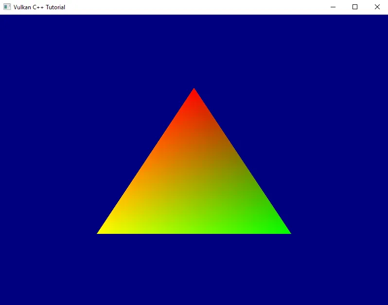
So we can now give each vertex an individual color and the interpolation works as we expect it. Nice.
Before we close for today I want to do a bit more refactoring: one thing that bothers me is the magic numbers we use to create the attribute descriptions in createGraphicsPipeline. Magic numbers are rarely a good idea. In this case they require us to change the pipeline creation code whenever our attribute format changes, which is cumbersome and error-prone. I want to fix that.
At first sight it seems we need the offset, the size and the format for each vertex attribute description. We also need the stride, i.e. total size of one vertex in bytes. But thinking a bit more about it: the offset is just the sum of all the previous sizes. The stride is just the sum of all sizes1. And the size is directly related to the format (after all we learned in the previous session that Vulkan uses the format to specify the size as well). So we actually only need the format.
Conveniently, Vulkan-Hpp ships a helper for exactly this: vk::blockSize( format ) from vulkan_format_traits.hpp returns the bytes per texel block, which for our uncompressed vertex formats is the size of one attribute. No hand-rolled switch required:
#include <vulkan/vulkan_format_traits.hpp>
...
auto createGraphicsPipeline(    const vk::Device& logicalDevice,    const vk::PipelineLayout& pipelineLayout,    const vk::ShaderModule& vertexShader,    const vk::ShaderModule& fragmentShader,    const vk::RenderPass& renderPass,    const vk::Extent2D& viewportExtent,    std::span< const vk::Format > vertexFormats) -> vk::UniquePipeline{    ...
    auto vertexAttributeDescriptions = std::vector< vk::VertexInputAttributeDescription >{};    std::uint32_t offset = 0;    std::uint32_t location = 0;    for ( const auto format : vertexFormats )    {        vertexAttributeDescriptions.push_back(            vk::VertexInputAttributeDescription{}                .setBinding( 0 )                .setLocation( location )                .setOffset( offset )                .setFormat( format )        );        offset += vk::blockSize( format );        ++location;    }
    const auto vertexBindingDescription = vk::VertexInputBindingDescription{}        .setBinding( 0 )        .setStride( offset )        .setInputRate( vk::VertexInputRate::eVertex );
    const auto vertexInputState = vk::PipelineVertexInputStateCreateInfo{}        .setVertexBindingDescriptions( vertexBindingDescription )        .setVertexAttributeDescriptions( vertexAttributeDescriptions );    ...}
We take the formats as a std::span< const vk::Format >2 so the caller can pass an array, a vector, or an initializer list without any conversion. We also had to reorder things a bit to streamline the calculations. But otherwise the code is pretty much the same as before, just with the vertex structure now defined from the outside. The only thing left to do is adapt the code in main() accordingly:
...constexpr auto vertexFormats = std::array< vk::Format, 2 >{    vk::Format::eR32G32B32A32Sfloat,    vk::Format::eR32G32B32A32Sfloat,};
...
while ( !glfwWindowShouldClose( window.get() ) ){    ...    pipeline = vcpp::createGraphicsPipeline(        logicalDevice,        *pipelineLayout,        *vertexShader,        *fragmentShader,        *renderPass,        swapchainExtent,        vertexFormats    );    ...}
Alright, that’s better. Now the pipeline implementation doesn’t need to change anymore when we change the vertex formats. We still have to manually adjust floatsPerVertex in main(), which isn’t ideal. I’m also not too happy with the way we currently create everything related to our vertex buffer directly in the main function, but I’m going to leave it for now until we have a bit more clarity where this is all going.
Next time we’re finally going to go 3D for real.
Footnotes
Section titled “Footnotes”-
This assumes that the vertex buffer is tightly packed. For performance reasons it might be better to pad the vertex data to reach a multiple of 16 bytes or so. In this tutorial we’ll keep things simple though and not look into that. ↩
-
We almost always know the attribute count at compile time, so a templated function taking a
std::arraywould avoid the heap allocation. I pickedstd::spanhere for ergonomics - it accepts arrays, vectors, and initializer lists alike, and this function is called rarely enough that the allocation isn’t worth optimizing away. ↩